• Skip to primary navigation
  • Skip to main content
  • Skip to primary sidebar
  • Skip to footer

Power Electronic Tips

Power Electronic News, Editorial, Video and Resources

  • Products
    • Power Supplies
    • AC-DC
    • DC-DC
    • MOSFETS
    • Power Management
    • Battery Management
    • RF Power
    • Resistors
    • Capacitors
    • Magnetics
    • Transformers
  • Applications
    • LED Lighting
    • Rack Mount
    • Wireless
  • EE Forums
    • EDABoard.com
    • Electro-Tech-Online.com
  • EE Learning Center
    • Design Guides
      • WiFi & the IOT Design Guide
      • Microcontrollers Design Guide
      • State of the Art Inductors Design Guide
  • Video
    • EE Videos
    • TI Power Videos
    • Teardown Videos
  • Resources
    • Design Fast
    • eBooks / Tech Tips
    • FAQ
    • LEAP Awards
    • Podcasts
    • Webinars
    • White Papers

Autonomous wireless charging keeps robots running

September 30, 2020 By Lee Teschler Leave a Comment

Buck-boost regulators efficiently power wireless charging stations for mobile robots.

Logistics, delivery and inspection industries increasingly rely on mobile robotic fleets. These fleets have become large enough that their users are trying to find ways of recharging them that don’t rely on human operators.

wibotic charging pad
An aerial drone landing on a WiBotic charging pad. The WiBotic charging system automatically manages both inductive charging when the receiver sits close to the power transmitter and magnetic resonance charging for situations like this one where the receiver sits some distance from the power transmitter.

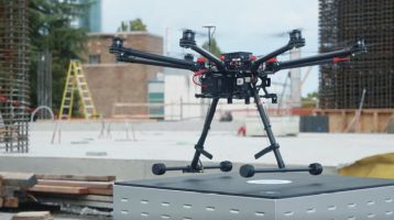
One means of automating the robotic charging process is through use of equipment from WiBotic. The approach is to build wireless charging hardware into the robotic platform. The charging hardware sends the bot to a charging station when it senses the battery needs a charge. The bot positions itself near the charging station in a way that aligns transmitting and receiving coils for power transfer.

The various possible configurations of ambulatory and flying robotic platforms complicate the design of the

wibotic components
The WiBotic wireless charging system components: Top, the transmitter unit and transmitter antenna coil. At bottom is the receive antenna coil and the onboard charger unit, connected to a battery pack being charged. The transmitter unit generates a high-frequency wireless power signal that travels through a coaxial SMA cable to the antenna coil. The transmitter recognizes any incoming robot equipped with an onboard charger and delivers the right amount of energy. Supported battery chemistries include lithium ion, lithium polymer, lithium iron phosphate, lead acid, and nickel metal hydride. Robots with completely different battery voltages can share the same transmitter unit which automatically recognizes each robot and adjusts charge parameters accordingly.

charging apparatus. Today, there are several ways of wirelessly charging batteries. The most common is inductive charging as is typical in cell phones. But inductive systems are only efficient when the antennas are extremely close. It’s tough to design robots and drones to position themselves accurately enough for reliable charging. Magnetic resonance charging offers more flexible positioning but has a relatively small sweet spot for maximum transfer efficiency.

WiBotic technology incorporates both inductive and resonant systems via what’s called an Adaptive Matching system. It constantly monitors relative antenna position and dynamically adjusts both hardware and firmware parameters to maintain maximum energy transfer efficiency across several centimeters of vertical, horizontal and angular offset. An embedded identification and communication system lets any robot charge from any station, even if the robots have different battery chemistries, voltages, and charging rates.

mobile robot
A fully autonomous mobile robot from Waypoint Robotics here moves toward a WiBotic wireless charging transmitter. The bot, which usually transports material in warehouses, has enough smarts to properly position itself next to the WiBotic charger. The WiBotic power transmitter-receiver adjusts power transmission mode to best suit the conditions at hand and the battery technology the Waypoint bot happens to carry.

APIs from WiBotic let computers on the same network as the transmitter monitor charging and set charging parameters. For example, operators might schedule robots for charging at their highest power level when they’re busy, but more slowly overnight to maximize battery lifespan.

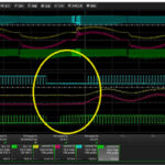
WiBotic chargers must carefully manage charging modes to optimize up-time while not degrading batteries through repetitive quick charges. This variability in charging cycles and power levels – from 300 W for fast charging to 100 mW trickle-charging – also requires a power delivery architecture that matches a wide range of impedances. To efficiently accommodate the wide range of loads, WiBotic used a Vicor zero-voltage switching (ZVS) buck-boost PRM regulator. Its topology enables a high switching frequency (about 1MHz). High switching frequency reduces the size of reactive components, enabling a power density of up to 1,383 W/in3. The Vicor regulator is integrated into the RF transmitter onboard the WiBotic TR-110 wireless charging station. The 48-V input (the regulator accepts a 36–75-Vdc range) is from an ac-dc power supply. The output voltage is dynamically controlled and trimmed from approximately 20 to 55 V as needed.

charging station PCB
Visible on the TR-110 wireless charging station PCB are the cooling fans that dissipate heat from the onboard RF amplifier. The Vicor surface-mounted PRM (not visible) sits outside this airflow.

The Vicor PRM handles full-charge and trickle-charge modes with no significant drop-off at lower power levels–a critical performance benchmark that defeated competing power components—as well as a ‘topping-off’ mode requiring a constant voltage for a 100% charge. High-efficiency conversion yielded a maximum operating temperature of 45°C. The TR-110 wireless charging station employs active cooling to dissipate heat from the onboard RF amplifier, but the Vicor surface-mounted PRM sits outside this airflow.

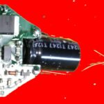
The zero-cross switching of the Vicor PRM module also minimized EMI/noise challenges and conducted emission/EMC requirements with no need for additional filters.

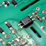
The PRM is in a surface-mount package measuring 1.28×0.87×0.249 in [32.5×22.0x6.31 mm] which is compatible with standard pick-and-place and surface-mount assembly processes. It also provides a planar thermal interface area to enhance thermal conductivity. The compact size of the PRM helps keep the onboard charger small and light weight, thus promoting long operating cycles particularly for airborne fleets. For the stationary wireless charging stations, a dense power delivery architecture ultimately helps conserve valuable real estate in the deployment environment.

You may also like:

  • safety standards
    Navigating new safety standards for power supplies
  • electrolytic caps
    Why electrolytic capacitors blow up

  • How to design modular DC-DC systems
  • energy harvesting
    What’s new in electrolytic capacitors and supercapacitors for energy harvesting
  • totem pole PFC
    How to select components for a digital-controlled Totem-Pole PFC

Filed Under: DC-DC, Featured, Power Management Tagged With: vicorcorporation

Reader Interactions

Leave a Reply

Your email address will not be published. Required fields are marked *

This site uses Akismet to reduce spam. Learn how your comment data is processed.

Primary Sidebar

CURRENT DIGITAL ISSUE

A frequency you can count on There are few constants in life, but what few there are might include death, taxes, and a U.S. grid frequency that doesn’t vary by more than ±0.5 Hz. However, the certainty of the grid frequency is coming into question, thanks to the rising percentage of renewable energy sources that…

More from the digital archive

DesignFast

Component Selection Made Simple.

Try it Today
design fast globle

Subscribe to our Newsletter

The Power Electronic eNewsletter delivers breaking electronic and power component news, resources, product innovations and more.

Subscribe today

EE TRAINING CENTER CLASSROOMS

EE Classrooms

RSS Current EDABoard.com discussions

  • Reducing switching noise in MOSFET inverter
  • LLC HB with synchronous rectifiers can be very dodgy?
  • ADS Cascode Power Amplifier Loadpull Problem
  • building lm2596 dc dc using Arduino uno
  • HFSS simulation problem

RSS Current Electro-Tech-Online.com Discussions

  • Where is the fuse ?
  • Capacitor to eliminate speaker hum
  • Test lead management ideas ?
  • PC/laptop working and processing so much harder on low quality connection
  • undefined reference header file in proteus

Footer

EE World Online Network

  • DesignFast
  • EE World Online
  • EDA Board Forums
  • Electro Tech Online Forums
  • Connector Tips
  • Microcontroller Tips
  • Analog IC Tips
  • Sensor Tips
  • Test and Measurement Tips
  • Wire and Cable Tips
  • 5G Technology World

Power Electronic Tips

  • Subscribe to our newsletter
  • Advertise with us
  • Contact us
  • About us
Follow us on TwitterAdd us on FacebookFollow us on YouTube Follow us on Instagram

Copyright © 2022 · WTWH Media LLC and its licensors. All rights reserved.
The material on this site may not be reproduced, distributed, transmitted, cached or otherwise used, except with the prior written permission of WTWH Media.

Privacy Policy