
Modern dc-dc converters can double as compact transient suppressors in vehicular electrical systems characterized by a lot of hash on the battery power lines.
By TIMOTHY HEGARTY, Non-isolated Power Solutions, Texas Instruments, Inc.
THE proliferation of electronic subsystems in vehicles has created a need for small, inexpensive and highly reliable electronics able to operate in challenging conditions. A number of these conditions arise because of noise on vehicle power rails. A vehicle battery’s steady-state range is 9 to 16 V, depending on its state of charge, temperature, and the condition of the alternator. However, the power rail is also subject to a range of dynamic disturbances, including start-stop, cold-crank and load-dump transient profiles.
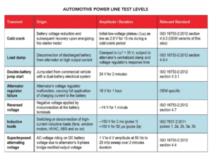
All these kinds of events create electrical conditions that can be problematic for electronics. To test for vulnerabilities, each vehicle manufacturer has its own extensive conducted immunity (CI) test suite, and there are standardized pulse waveforms given by international standards such as ISO 7637 and ISO 16750. Besides common sources of undervoltage and overvoltage transients, alternator sinusoidal-profiled noise superimposed on the dc bus can be deleterious, particularly for vehicle infotainment and lighting systems.
Most vehicles try to head-off transient disturbances using a passive circuit consisting of a low-pass inductor plus capacitor (LC) filter and transient voltage suppressor (TVS) array. Automotive electronics sitting downstream from the protection network are then rated to survive up to a 40-V transient without damage. But the inductor/electrolytic capacitor combination needed for attenuating disturbances at low frequencies takes up a lot of space.
Fortunately, there is a more compact way of dealing with transients. It involves an active filter using a synchronous buck-boost dc/dc converter having a high power supply rejection ratio (PSRR, where rejection expressed as a log ratio of output noise to input noise). Besides handling filtering, the active filter also provides both battery voltage regulation and transient rejection.
SYNCHRONOUS BUCK-BOOST CONVERTER
When devising regulators that work with vehicle batteries, designers must keep in mind that the battery voltage can be above the output voltage setpoint (as when the battery is charging), below the setpoint (as when severely discharging), and equal to the setpoint. This variability calls for a buck-boost conversion. Traditional buck or boost converters are inadequate here because only a step-down or step-up conversion is possible, respectively.
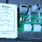
A four-switch synchronous buck-boost converter can be designed around an LM5175-Q1 controller to output a tightly-regulated 12-V rail. This approach works well for engine management units (EMU) and other critical automotive functions where loads must remain powered without glitches during even the most severe battery-voltage transients.
The main attraction of this modern buck-boost power stage is that simple buck or boost operating modes are used to realize a high conversion efficiency. The circuit produces a positive output voltage in contrast to the classic single-switch (inverting) buck-boost. And, by virtue of its simple magnetic component, it exhibits less power loss and higher power density relative to SEPIC, flyback, Zeta, and cascaded boost-buck topologies.
The four-switch buck-boost converter has an intuitive topology. It is also relatively compact and goes through a controlled startup while incorporating short-circuit protection in boost mode. As well, the control and compensation is simple and the converter uses a constant-switching frequency. As such, this approach works well for automotive battery voltage regulation.
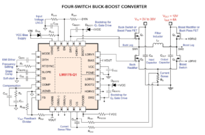

A schematic of a typical four-switch buck-boost converter circuit specifies components for a power stage and a LM5175-Q1 controller chip. The controller chip includes integrated gate drivers, a bias supply, current sensing circuits, output voltage feedback, loop compensation, a programmable under-voltage lock-out circuit, and a dither option for lower noise signature. The designer can choose a switching frequency. A 400 kHz switching frequency will minimize the circuit footprint and eliminate interference with the AM broadcast band.
In the accompanying schematic, four power MOSFETs are arranged as buck and boost legs in an H-bridge configuration, with switch nodes SW1 and SW2 connected by a power inductor, designated LF. Conventional synchronous buck or boost operation takes place when the input voltage lies suitably above or below the output voltage, respectively, and the high-side MOSFET of the opposite, non-switching leg conducts as a pass device.
However, the most compelling feature of this particular buck-boost implementation is that it employs a special scheme in the buck-boost (B-B) transition region when the input is close to the output voltage setpoint. Then, both buck and boost legs each switch at half the switching frequency in a phase-shifted, interleaved manner that is particularly advantageous for efficiency and power loss.
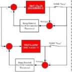
A control architecture that combines peak current-mode control in boost and valley current-mode control in buck enables smooth mode transitions, requiring just one low-side configured shunt resistor for current sensing.
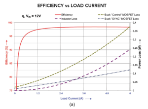
 It is interesting to view plots of efficiency and component power dissipations versus line and load for the accompanying converter design. Considering losses in totality, a converter with 12-V regulated output quite readily hits efficiencies in excess of 95% across wide ranges of output current and input voltage.
One important property for vehicular electronics is immunity to conducted transients in the audio frequency (AF) range. A source of this noise is the automotive alternator which has a residual alternating current on its output. The alternator’s stator winding is basically a three-phase sinusoidal current source with high-impedance output feeding into a diode full-wave rectifier. The rectification creates overlapping current pulses and the ripple is determined from the three phases.
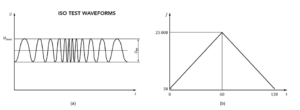


ISO 16750-2 section 4.4 describes the voltage ripple on the alternator’s output that vehicular electronics should be able to withstand. The test signal is in the frequency range of 50 Hz to 25 kHz with an amplitude of 1 V, 2 V and 4 V peak-to-peak, depending on the test pulse severity.
MAXIMIZING PSRR
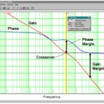
PSRR of a dc/dc converter is related to and affected by loop bandwidth. The loop bandwidth is typically limited to 20% of the switching frequency or lower, depending on the right-half-plane zero (RHPZ) frequency that appears when operating in boost mode. In a controller such as TI’s LM5175-Q1, PSRR performance is largely independent of VIN and load changes. This is thanks to a current-mode control scheme with adaptive slope compensation, based on the difference of VIN and VOUT, that is designed to raise PSRR and reject line transients.
In the accompanying schematic, the capacitor designated CSLOPE establishes the slope compensation setting. CSLOPE is chosen for an idealized deadbeat response at the classic one-times the inductor upslope (downslope) in valley (peak) current-mode buck (boost) mode of operation. A setting of half the applicable inductor slope theoretically provides optimal line rejection, but this represents the minimum slope compensation for loop stability.
All in all, the four-switch synchronous buck-boost converter is a compact and economical way of realizing tight voltage regulation in automotive applications. It obviates the need for bulky passive filter components. The buck-boost controller also has an AEC-Q100 automotive qualification.
REFERENCES
Singh, Atul. “Load dump and cranking protection for automotive backlight LED power supply,” TI application report (SNVA681A), March 2015
“ISO 7637-2:2011, Road vehicles – electrical disturbances from conduction and coupling,” ISO standards website
“ISO 16750-2:2012, Road vehicles – environmental conditions and testing for electrical and electronic equipment,” ISO standards website
“Front end power supply reference design with cold crank operation, transient protection, EMI filter,” TI Design (TIDA-00699)
Hegarty, T. “Optimizing the efficiency of the 4-switch buck-boost converter,” How2Power, September 2015
Choudhary, V. and Jacob, M. “Smart diode and 4-switch buck-boost converter provide ultra-high efficiency, compact solution for 12-V automotive battery rail,” PCIM Europe, Nuremburg, May 10–12, 2016
LM5175EVM-HD 400 kHz high density buck-boost converter EVM, Texas Instruments
“Automotive cranking simulator user’s guide,” Texas Instruments (slvu984)
Leave a Reply