
Part 1 of this FAQ discussed development and designation of basic DC power rails. Part 2 looks at key specifications of these rails, and management of single- and multi-rail systems.
Q: What’s an important point to remember whenever discussing voltage?
A: The tendency is to say “this voltage rail is at such-and-such voltage” or “the voltage at this point is such-and-such.” However, this phrasing can lead to misunderstandings. The reason is simple: there is no such thing as a voltage at any given point.
Q: That seems to contradict standard usage, what’s going on?
A: The term voltage is really another way of saying “potential difference” which is what a “voltage” is. In other words, a voltage only has meaning between two defined points. Thus, when you say the voltage at Point A is “x volts”, you have to keep in mind the other point with respect to which you are calling out that voltage. Is it a 0-V rail? Is it “ground,” whatever that means? Is it another point in the system? Are the ground (if any) and 0-V point the same (most likely not)?
Q: So when I read a data sheet, and it calls out, for example, VCC = 3.3 V for an IC, what does that mean?
A: It means the voltage as measured with respect to the common or so-called “ground” terminal of the IC. For “floating” devices or components, such as a non-grounded sensor, you have to be careful with how and where you define voltages such as the output of that sensor.
Q: How close to nominal value must the DC supply rail be?
A: The answer is “it depends”. Different components (loads) and vendors will call out different tolerance standards. Typically, a rail which is in the low single digits, such as 3.3 V, must be within 2 % to 5%, but some components have tighter requirements such as 1%. That’s why some systems use multiple supplies at the same nominal voltage, with a tight-tolerance, more-expensive DC rail for some components and a less costly one for the 5% ones. Keeping track of all the rails and their tolerances is an important task.
Q: What about the tolerance with higher rail voltages such as 15, 24, or 48 V?
A: In general, these rails are specified to be accurate to a few hundred millivolts of their nominal value, but again, the key factor is what the data sheet for the load components can accept. Further, you may need to take into account temperature coefficient and drift of the supply, which can cause its output to shift further from nominal as it heats up (whether due to self-heating or the systems ambient heating.
Q: What about ripple?
A: Ripple is a small AC-like waveform superimposed on the DC rail, and it is a by-product of the DC/DC switching regulator operation, Figure 1. The amount of ripple is a function of the design and implementation of the DC/DC circuit. Ripple is a form of noise and can affect circuity performance and consistent operation.

Q: How much ripple is acceptable?
A: As always, it depends on the system and its components. Typically, ripple should be on the order of 50-100mV maximum, but instrumentation and low-voltage applications may need lower ripple, around 10 mV. Special low-ripple DC/DC regulators are available which are optimized for lower ripple, sometimes at a higher cost or needing some additional external passive components.
Q: In a simple single-rail system, are there any issues other with which to be concerned?
A: Once the power rail is at nominal value, the only issue is if the supply can deliver the needed current. But there are often issues with power turn-on and turn-off. The rate at which the DC rail ramps up from “off” (zero V) may affect circuitry start-up. Some components need to have the rail transition at a fast, but not too fast, rate; if too slow, the component may not initialize itself properly; the rail should also not overshoot nominal at start up and possibly damage a component.
Q: What can be done if the power-rail turn on transition is too slow or too fast?
A: The simplest solution is to “gate” the supply rail with a FET which is controlled by a digital control line, if available. However, the basic FET has some shortcomings in control. Instead, a tiny, four-terminal FET-based device called a load switch is often a better choice since it can be set up to control the timing of the power-rail rise (and fall), Figure 2, and transparently offers other functions as well, Figure 3. The load switch, in turn, is controlled by a digital signal from a small, guaranteed-to-start subcircuit or external line.

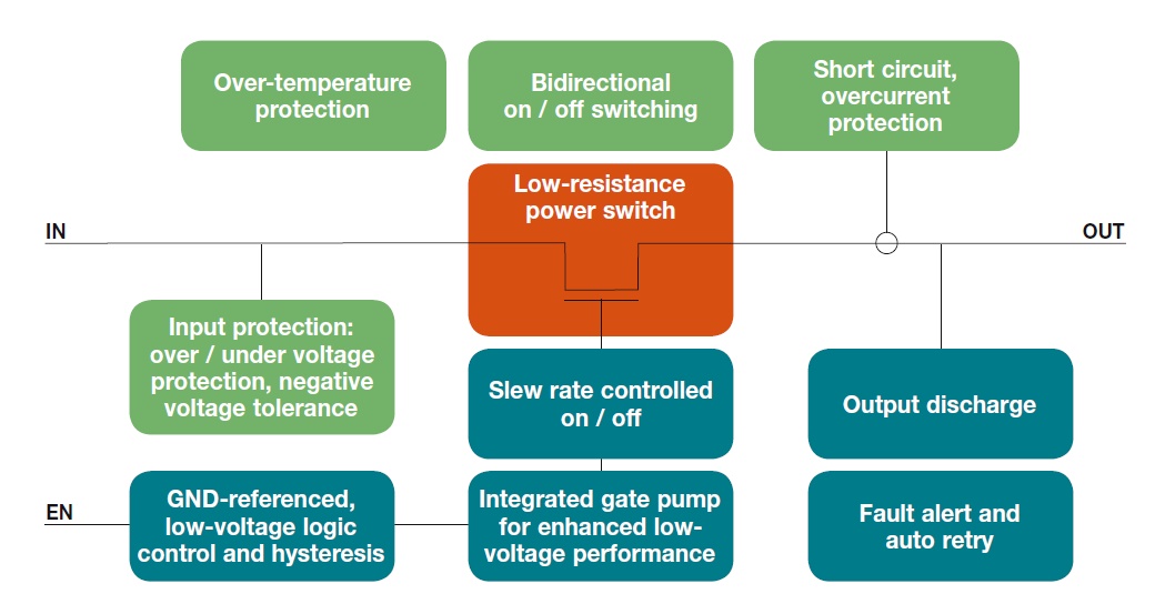
Fig 3: A load switch is more than just a FET; it usually includes other needed functions, and they are self-managed without system or software intervention. (Image Source: Vishay Siliconix)
Q: What about situations with multiple rails?
A: The ramp-up and ramp-down situation is more complicated with multiple trials. Many multi-rail ICs, such as FPGAs or communications ICs, have strict sequencing specification mandating, for example, that a specific rail must reach its nominal value within a defined number of microseconds before another specified rail is turned on.
To manage this situation, the design can use multiple load switches, or instead a single, larger component called a power management IC (PMIC). A PMIC includes the load switches and also allows the user to set-up the timing of the switches with respect to each other. A PMIC also usually has other protection circuitry to ensure that no power is applied if any of the source rails is out of specification or not present.
As you can see, the apparently “simple” issue of supply rails has many issues and subtleties. However, time spent making sure that the rails are within speciation and turn-on/off properly is a good investment, since power rails are the foundation on which consistent circuit and system performance critically depends. Any deficiencies or deviations in these rails can cause frustrating issues and troubleshooting headaches both at the prototype and evaluation stages as well as in the field.
Leave a Reply