
Fuses, eFuses, various types of thermistors, and fusible resistors can provide varying levels of circuit protection. Fuses offer only the most basic level of overcurrent and short-circuit protection. Thermistors can be added to provide inrush current control, and a fusible resistor can provide both inrush current control and overcurrent/short-circuit protection. The most comprehensive protection is provided by eFuses, which can protect from short circuits, over-currents, over-voltages, reverse current, over-temperatures, and can even control inrush currents. This article considers the tradeoffs when using these different circuit protection technologies and briefly reviews which types of applications each one is best suited for.
Fuses
In a fuse, a metal wire or strip melts due to Joule heating when too much current flows through it, providing over-current and short-circuit protection. Joule heating, also known as resistive, resistance, or Ohmic heating, results from electric current flowing through a conductor. Fuses are single-use devices. The melting point is imprecise and is impacted by ambient temperature, the profile of the current increase, and other factors. In addition, the relatively slow reaction times of fuses (1 second or longer) increase system stresses and reduce long-term system robustness.
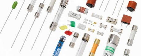
Fuses are available in axial- and radial-leaded cartridges and surface-mount packaging (Figure 1). The definition of a ‘fuse’ varies between the IEC and UL/CSA. A ‘fuse’ is the assembly of a fusible link and a fuse holder in IEC standards. In UL/CSA standards, the fuse is the replaceable portion of the assembly, and the metal conductor that melts is the fusible link.
UL 248 currently has multiple sections. UL 248-1 sets the general requirements for fuses, while the other sections define specific fuses sizes or define fuse applications with specific performance requirements, such as 248-13, which defines semiconductor fuses, and 248-19 defines photovoltaic fuses. The general requirements (248-1) apply except as modified by the supplemental section. For example, UL 248-19 allows photovoltaic fuses to be rated up to 1500 VDC versus 1000 V, as defined in 248-1.
Fuses can be mounted in a variety of ways:
- They are directly soldering the fuse on the PCB. This is often done with surface-mount fuses. While mounting costs can be minimized, maintenance is more complicated if a blown fuse needs to be replaced.
- Fuse clips soldered to the PCB are relatively inexpensive and allow for field replaceability. Fuse clips are limited to 30A or less. They are generally not listed or recognized by safety agencies. Removing a fuse from a fuse clip requires opening up the piece of equipment, resulting in a safety hazard if the equipment is still energized.
- Fuse blocks are designed for larger amperage applications. Fuses mounted in fuse blocks are typically only accessible by opening the piece of equipment, leading to electrical shocks if the equipment is not disconnected from the power source.
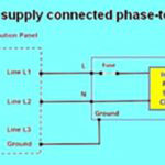
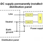
- Panel mounted fuse holders enable easy access for the end-user to replace the fuse in the field. Removing the fuse is safe since, when the cap is removed from the fuse holder, the fuse circuit is disconnected, preventing any possibility of electrical shocks. Fuse holders are approved by safety agencies and are available with ratings up to 30A.
- Inline fuse holders built into wire harness assemblies. Inline fuse holders can typically handle 30A in high-voltage (AC line voltage) applications and up to 100A in lower voltage installations.
Thermistors for inrush current control and over-current protection
Positive temperature coefficient (PTC) and negative temperature coefficient (NTC) thermistors are used for over-current protection and inrush current control, respectively. An NTC thermistor has an inverse relationship between temperature and resistance; as its temperature increases, its resistance decreases. For a PTC thermistor, as temperature increases, resistance also increases.
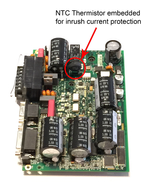
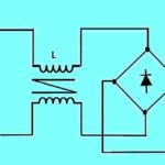
An uncontrolled flow of inrush current can damage the diode bridge and link the capacitor of power supplies, motor drives, battery chargers, and other AC-input power converters. An NTC thermistor is often used to control the inrush current. When the device is cold at turn on, it has relatively high resistance (Figure 2). An NTC thermistor heats up as current flows, and the resistance drops, allowing higher current to flow following a turn-on period.
A PTC thermistor can be used to provide short-circuit protection. Excessive currents heat the device causing its resistance to rise and limit the current. Simple PTC thermistors are found in industrial and extreme temperature environments where equipment may experience frequent shorting and needs fast reset times. They are not generally found in electronic systems.
Polymeric positive temperature coefficient PPTC devices sometimes provide Overcurrent protection in electronic systems. The hold current of a PPTC device is its continuous current rating; up to that level, the device is guaranteed not to trip. The trip current is the current at which the device is guaranteed to get hot enough to trip. A small current (up to a few hundred milliamps in some devices) continues to flow through the device and maintains a high enough temperature to keep the PPTC in a high-resistance state. Once the trip current is reached, the resistance increases substantially and reduces the current.
When power is removed, the PPTC device cools and returns to a low-resistance state. Depending on the device and ambient/operating conditions, the cooling can occur in a series of stages. A PPTC device will conduct the hold current within a few seconds, but it may still be at a slightly higher resistance than before tripping. Like fuses, PPTC devices are relatively imprecise and provide slow-acting protection. The benefit of using a PPTC device is its revertability once a fault condition has been removed.
Fusible resistors
Fusible resistors combine a fuse and a current-limiting resistor in a single component, reducing cost and freeing up PCB space (Figure 3). Fusible resistors are available using film and wire-wound technologies. Fusible film resistors can be a good choice for lower power applications where surge- and overload-handling demands are low to moderate. Applications that are expected to experience higher surge voltages and higher temperatures benefit from using wire-wound fusible resistors.
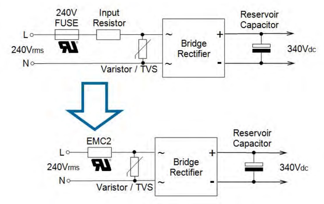
Fusible resistors typically have resistance values from 1 to 30 Ω compared with fuses with resistances ranging from milliohms to hundreds of milliohms. The fusing times of most fusible resistors are similar to those of conventional fuses. Some fast-acting fusible resistors can react to sudden fault events, with fusing times < 20 µsec. A fusible resistor can replace both a fuse and resistor (or NTC thermistor to improve operating efficiency) on the input of an AC rectifier circuit. An NTC thermistor has a resistance that can be as high as 10 or 20 Ω initially, similar to that of a fusible resistor or conventional resistor. Still, its resistance drops to tens of milliohms during steady-state operation.
In contrast with fuses, which are rated in terms of current, fusible resistors are rated in terms of power-handling capacity. Typical fusible resistors are rated from 2W to 25W and provide isolation levels from 250V to 500V. Fusible resistors are covered under the UL1412 standard. Some fusible resistors are offered with coatings that meet UL94-V0 standards, and they will not burn or emit incandescent particles under any condition of applied temperature or power overload.
eFuses
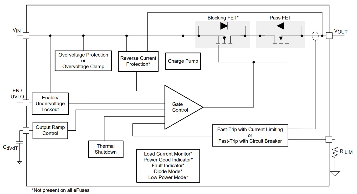
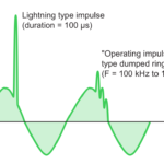
A circuit protection IC called an ‘eFuse’ can overcome the limitations of fuses, PPTC devices, and fusible resistors and provide additional levels of protection. eFuses protect from short circuits, over-currents, over-voltages, reverse current, and over-temperatures, and can even control inrush currents (Figure 4). An eFuse is more accurate and faster-acting than fuses, PPTC, or fusible resistors. For example, an eFuse reacts in hundreds of nanoseconds, compared with one second or longer for other protection devices. And an eFuse reacts instantly once the fault reaches a predetermined level, such as 160% of the maximum current setting.
eFuses are available in latching and auto-retry designs and can be used multiple times compared with single-use fuses or fusible resistors. Once activated by a fault condition, latching eFuses remain off until the power is cycled OFF, then ON again, or a signal is sent to an ‘enable’ pin, depending on the design. Auto-retry eFuses continue to recycle the power themselves at a fixed interval, usually several hundred milliseconds, until the fault is cleared. eFuses can be recognized as Solid State Overcurrent Protectors under the UL2367 standard and certified under the UL60950 safety standard.
Summary
As shown, designers can choose fuses, eFuses, various thermistors, and fusible resistors to implement circuit protection. Each technology provides a unique set of performance and cost tradeoffs. eFuses offer the most complete suite of protection functions. They can protect equipment from short circuits, over-currents, over-voltages, reverse current, and over-temperatures, and can even control inrush currents. All of the other circuit protection options provide considerably less capability but are well suited for specific application scenarios.
References
Basics of eFuses, Texas Instruments
Fuseology Application Guide, Littelfuse
PTC Thermistors vs. NTC Thermistors for Inrush Current, Ametherm
UL Recognized Fusible Resistors Application Note, TT Electronics

eFuses, to my knowledge, have not been evaluated for their reliability to perform the inherent safety functions that have been mentioned in this article. Both UL standards mentioned (UL 2367 and UL 60950) do not have the appropriate requirements to assess the reliability of the microelectronics for functional safety.