
A silicon controlled rectifier (SCR) is a four-layer power semiconductor device. The term ‘silicon controlled rectifier’ was coined by General Electric when SCRs were first introduced in 1957. Like rectifiers, SCRs are unidirectional devices. Today, SCRs are recognized as a type of thyristor. Other types of thyristors, such as triacs, are inherently bidirectional. This FAQ looks at basic SCR operation and SCR operating modes, and concludes with a review of some advanced digital power control techniques applied to SCR power converters.
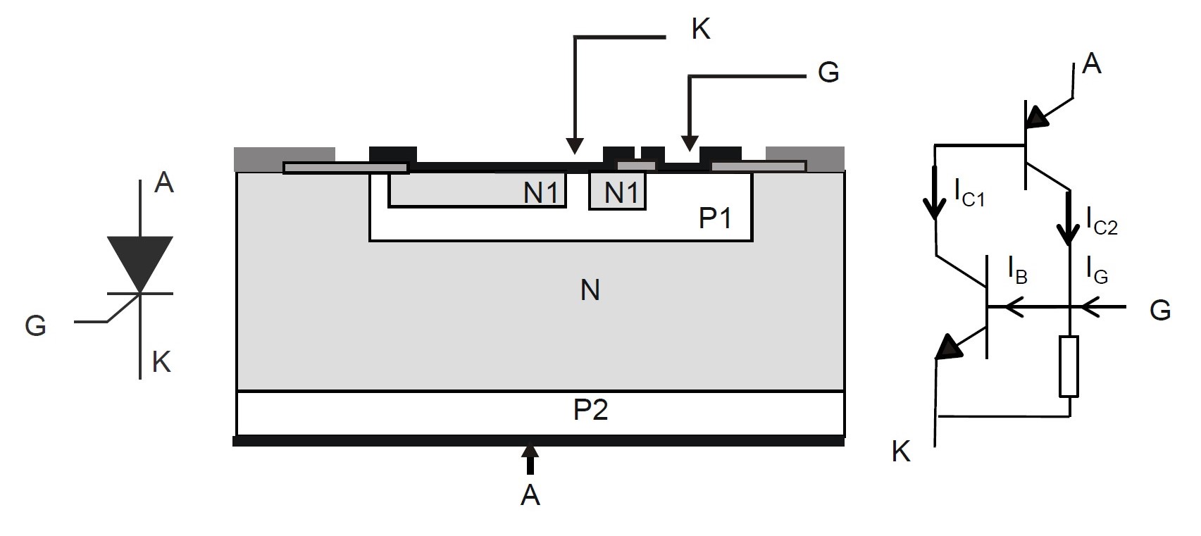
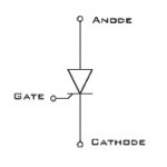
As a basic thyristor, an SCR can be viewed at two bipolar transistors (one NPN and one PNP), where one of the transistors serves as the control (gate) connection and the second transistor provides the cathode and anode connections for current flow (Figure 1). For basic SCRs, the gate is connected to the base of the NPN transistor. As a result, it’s triggered by a positive gate current from G to K. Once the gate current is applied to the NPN device, it draws collector current amplified by βNPN, the NPN current gain (IC1 = βNPN x IB), and the collector current is sunk from the PNP base. In turn, the PNP base current is amplified by the PNP current gain (βPNP). This results in a regenerative condition, and the SCR latches on when the βNPN x βPNP product reaches one. When that happens, the gate drive can be removed. The minimum anode current needed to keep the thyristor on is called the latching current, IL. The device turns off when the anode current drops below IL.
Benefits of using SCRs include:
- Symmetric withstand voltage withstanding enables an SCR to work in ac voltage applications without adding a diode in series
- A high overcurrent capability ensures reliable operation where large current surges can be anticipated, such as overvoltage protection crowbars, capacitor discharge circuits, and motor controls
- Control by a gate current allows a simple triggering circuit to be used without a complex voltage supply.
- The ability to remain latched on even after the gate control signal has been removed
- Zero-current turn-off, which is useful in phase control dimmers and inverters that benefit from zero current switching operation
- Overvoltage with stand ruggedness
SCR operating modes
SCRs have three operating modes (Figure 2):
- Reverse blocking (off state)
- Forward blocking (off state)
- Forward conduction (on state)
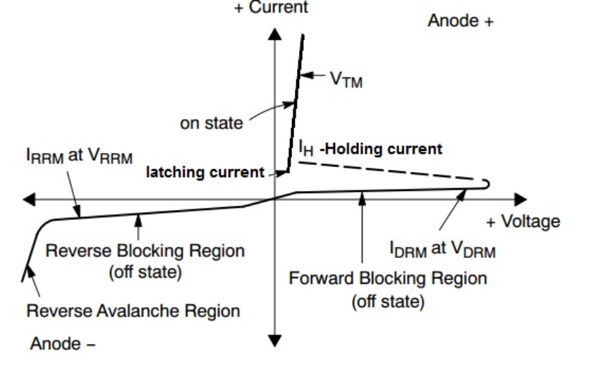
Reverse blocking
Reverse blocking occurs when a positive voltage is applied to the cathode and a negative voltage on the anode. The SCR behaves like two diodes connected in series with only a small leakage current flowing. If the reverse voltage increases to a critical level, the reverse breakdown voltage (VBR), an avalanche occurs, and the reverse current quickly rises in the reverse avalanche region.
SCRs are available with enhanced reverse blocking capability. They have a larger forward voltage drop, but the forward and reverse blocking voltage ratings tend to be the same. An SCR that can’t block a reverse voltage is called an asymmetrical SCR, ASCR, and has a reverse breakdown rating of a few tens of volts. ASCRs are used in applications where a reverse voltage cannot occur, such as switching power supplies or in combination with a parallel reverse conducting diode.
Forward blocking
Forward blocking occurs when a positive voltage is applied to the anode, and a negative voltage is applied to the cathode, with the gate at zero potential. Only a small leakage current is flowing. When the applied voltage reaches the breakover level, avalanche breakdown occurs, and the SCR begins conducting.
Forward conduction
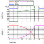
There are two ways to turn on an SCR. As noted above, an SCR will begin conducting if the applied voltage reaches the breakdown level. Alternatively, applying a positive pulse at the gate will turn on the device. Once an SCR starts conducting, the gate voltage can be removed, and the device will remain in the on state until the current flowing through the device drops below IL. In addition to turning off when the current drops below IL, an SCR can be turned off with a brief short-circuit applied between the anode and cathode with the gate turned off.
Reverse conducting SCRs
Asymmetrical SCRs can be produced by co-packaging an SCR and a reverse conducting diode. This structure is called a reverse conducting thyristor, RCT. The reverse diode prevents the thyristor from blocking reverse voltages. RCTs are used in applications that benefit from having a freewheeling reverse diode, such as inverters or frequency changers. Since the SCR and diode never conduct simultaneously, they do not produce heat simultaneously, reducing heat buildup and simplifying thermal management.
Digital control for SCRs
Phase-angle mode is often used in SCR applications such as heating and lighting because of its ability to deliver specific amounts of power precisely. Low power factor and high levels of harmonics are produced when using phase-angle control, making it unsuitable for many applications. Modern digital controllers for SCRs can offer several alternative operating modes (Figure 3):
- Zero-cross mode (TAKT) is a full-wave switching mode that creates no harmonics. This mode is also able to drive transformer-coupled loads while minimizing inrush current.
- Voltage sequence control (VSC) can provide fast response, high control dynamic, and high control resolution per cycle, like phase-angle mode, but without generating the harmonics and noise.
- Voltage transition (VT) mode combines zero cross and phase-angle firing and is frequently used for applications that are not transformer-coupled. VT mode combines the advantages of TAKT and phase-angle modes.

Additional digital control modes have been developed for application-specific requirements. For example, the MoSi mode has been developed for molybdenum disilicide (MoSi) based heating elements with very low cold resistance and high thermal inertia. A MoSi controller can be used in heating applications with high hot/cold resistance ratios to ramp up quickly to the target temperature in phase-angle mode and then switch automatically to zero-cross mode to maintain the temperature.
Summary
An SCR is a four-layer power semiconductor device also known as a thyristor. It consists of one NPN bipolar transistor and one PNP bipolar transistor integrated into a single structure where one of the transistors serves as the control (gate) connection and the second transistor provides the cathode and anode connections for current flow. The SCR characteristic curve includes two off states and one on state. SCRs are a mature technology, but advanced digital control techniques have enabled their use across a range of sophisticated applications.
References
Basics on the thyristor (SCR) structure and its application, STMicroelectronics
Silicon controlled rectifier, Wikipedia
The Many Benefits of SCR Power Control, Advanced Energy
What You Need to Know about SCR Power Controllers, Advanced Energy
Leave a Reply