
Current sensing and measurement are important in applications such as power conversion, battery charging, and industrial processes. Different current sensing technologies are used, depending on whether the measurement is for alternating current (AC) or direct current (DC) and how much current needs to be measured.
This FAQ reviews Hall effect, and induction sensing and resistive shunts, and discusses relative performance, appropriate applications, and costs, and looks at the use of current sense amplifiers and filtering.
A magnetic field is produced around a current-carrying conductor proportional to the amount of current flowing. The amount of current flowing can be determined by measuring the magnetic field. There are two primary ways to measure the magnetic field around a conductor; Hall effect devices can be used to measure DC as well as AC, while inductive sensors can be used to measure AC (Figure 1).
A Hall effect sensor consists of a core, a Hall effect device, and signal conditioning circuitry. The conductor carrying the current to be measured passes through a magnetically permeable core that concentrates its magnetic field. The Hall effect device is mounted at a right angle to the concentrated field and is energized by a constant current in one plane. When the energized Hall device is exposed to the concentrated magnetic field from the core, it produces a differential voltage that is measured and amplified by the signal conditioning circuitry to produce an output proportional to the current.
Hall sensors are isolated from the monitored current and voltage, minimizing safety concerns. In addition, Hall effect sensors can be designed to provide repeatable and accurate measurements of AC and DC. However, Hall devices have some disadvantages:
- Hall effect devices can require more energy than inductive sensors or shunts
- Hall effect devices can have more limited measurement ranges compared to inductive sensors
- Hall effect devices can be more expensive than inductive sensors or shunts
An inductive current sensor is used to measure AC and consists of a wire-wound core and a signal conditioner. The current conductor passes through the magnetically permeable core that magnifies the conductor’s magnetic field. The AC causes the magnetic field to expand and collapse, which induces a current in the windings. Compared with a transformer, the current-carrying conductor is analogous to the primary, and the core is the secondary. The secondary current is converted to a DC voltage, and the conditioning circuitry produces an output proportional to the current being measured. Inductive sensors typically operate between 20 and 100 Hz, but there are devices on the market that work up to 1 kHz and even 1 MHz. Inductive current sensing is inherently isolated from the voltage being sensed and can provide high accuracy and a wide sensing range. Both inductive sensing and Hall effect devices produce a near-zero insertion loss (voltage drop) on the monitored circuit. Shunts are more rugged and lower in cost than inductive sensing and Hall effect devices, but their use always involves a measurable voltage drop on the monitored circuit.
What about shunts?
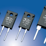
A shunt is simply a low-Ohm resistor used to measure current. Shunts are available across a wide range of currents and voltages and can be used to measure currents of thousands of amps or milliamps (Figure 2). The current to be measured flows through the shunt, which is connected in parallel with the measuring circuitry or device. Using a shunt invariably involves a voltage drop and heat generation; hence, using very low resistance on the order of a few milliohms or less is an important consideration.
Shunts are precision resistors based on Ohm’s law: V = IR, where V = voltage drop, I = current flow, and R = shunt resistance. Shunts can be used to measure AC or DC and typically produce a voltage drop of a few millivolts. When used to measure AC, shunts present operational challenges and safety concerns. When used to monitor AC in an industrial environment, shunts (typically not insulated) can carry 480 Vac and present a shock hazard. In addition, in 480 Vac environments, the associated signal conditioner must be designed to withstand the high voltage. It can be expensive, negating some of the benefits of using a low-cost shunt. When measuring high currents, shunts can need cooling. Even then, they can be very hot and represent a potential burn hazard. And the heat generated by a shunt reduces overall system efficiency and wastes energy. Shunts have several advantages in industrial environments:
- Shunts are rugged and can withstand high overcurrent levels
- Faults can be quickly detected, making shunts useful in safety-related applications
- Shunts provide precise current measurements, making them useful in applications such as motor drives or battery management systems
- Shunts tend to be low cost and have high reliability
Metal film vs. full metal
Shunt resistors are available using metal film or full metal constructions, each with different cost/benefit tradeoffs. For example, metal film shunts are less expensive, but their temperature coefficients are inferior to full metal shunts. In addition, their construction interferes with current measurements. Metal film shunts consist of a paste applied to a ceramic substrate and laser trimmed to the desired resistance. Laser trimming is good and can result in high accuracy. The heterogeneous nature of the materials used is not good and results in inductance (L), and the basic Ohm’s law does not necessarily apply. The formula for the voltage drop in a metal film shunt is: V = I x R – (L x (di/dt)), where di/dt is the rate of current change over time, increasing the complexity of determining the actual current.
Full metal shunts can be more expensive than metal film devices, but their homogeneous structure produces more consistent and undistorted measurements. Since no additional inductance exists, these devices are suited for high-precision applications such as medical engineering or test and measurement equipment. They are more thermally rugged than metal film devices, are available in form factors much larger than standard chip resistors, and can be used to measure single-digit milliohms of current accurately.
Four-wire shunts
Applications that demand high precision can benefit from using four-wire shunts where the current to be measured flows through two terminals and the voltage is measured at the other two terminals. The separation of current and voltage terminals eliminates the lead and contact resistance from the measurement. This is an advantage for the precise measurement of low current values. Four-terminal sensing is also known as Kelvin sensing. Each two-wire connection can be called a Kelvin connection. Four-wire shunts are useful when:
- The line and contact resistance are relatively high and are not negligible relative to the measured resistance.
- The resistance value is less than ten milliOhms (mΩ), as the resistance values of the conductors are also measurable in mΩ and must thus be incorporated.
Current sense amplifiers and filtering
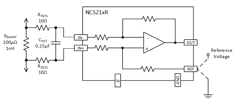
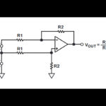
Filtering at the input or output of a current sense amplifier may be required for several reasons. For example, for current sense amplifiers, thin-film shunt resistors of 1 mΩ or less are used. Thin-film resistors below 1 mΩ can have a shunt inductance that causes transient spikes on the current sensing line and can overload the front end of the current sense amplifier.
In applications where the current being measured is inherently noisy, filtering after the output of the current sense amplifier can be the best approach, especially if the amplifier output is connected to high impedance circuitry. Other applications, such as dc/dc converters and power supplies, may also require filtering at the current sense amplifier’s input.
For example, shunt inductance can significantly affect frequency response as the shunt resistors decrease in value. At values below 1 mΩ, the shunt inductance can cause a zero in the transfer function, resulting in corner frequencies in the low 100s of kHz. The shunt inductance increases the amplitude of high-frequency spike transients on the current sensing line and can overload the front end of the shunt current sensing IC. Adding filtering to the input of the amplifier can correct this problem (Figure 3). Filtering can be needed even if the spike frequencies are above the rated bandwidth of the current sensing IC.
Summary
Designers have a variety of current sensing technologies to select from, including Hall effect devices, inductive sensors, metal film, and full metal shunts. The various sensing technologies offer varying safety, thermal challenges, precision and accuracy, and cost combinations when designing current sensing circuits. In some applications, it’s necessary to compensate for parasitic inductances and use filtering techniques to ensure robust and accurate current measurements.
References
Current Sense Amplifiers: Input and Output Filtering, onsemi
Current Sensing Theory, NK Technologies
How is current measured using shunts?, Rutronik

Leave a Reply