
Nanopower ship mode and sleep mode can be optimized to reduce power consumption.
Suryash Rai • Analog Devices Inc.
In the connected world of the internet, power management is an important way to boost the efficiency of IoT applications. In most situations, the sensor node (data 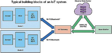 acquisition element) sits in a remote area and is powered by a battery. Battery life depends on the efficiency of power strategies for the sensor node. Most of the time, the sensor node stays in sleep mode and switches to active mode only when it must acquire data. The duty cycle of sensor node devices is low. Thus to maximize the battery life, the best strategy is to reduce the sleep current.
Because overhearing (that is, when a sensor node receives a data packet destined for other nodes in the network) and idle listening are major sources of energy waste in the sensor node, we can evaluate a wireless sensor node’s power consumption using three different areas: the sensor, the microcontroller, and the radio operation.
The sensor collects raw data like temperature and humidity and sends it to the MCU. The MCU processes the raw data and transmits it to the cloud or data center via a radio link. However, typical sensor applications operate at extremely low duty cycles (ranging from 0.01% to 1%) and are idle most of the time. So adopting a power management scheme that keeps sensor node sleep current ultralow will conserve battery life. An example would be a smart irrigation system where the sensor node measures the soil moisture and collects data only hourly.
The ship mode and sleep mode are common jargon used in battery-operated IoT devices and are crucial aspects of power management. The ship mode is a nanopower state that prolongs battery life during the shipment stage of a product. In ship mode, the battery is electrically disconnected from the rest of the system to minimize power drain while the product is idle or unused. Push-buttons release the ship mode and start the normal operation of the device.
Once the device is active, sleep mode serves to extend the battery life. In sleep mode, all the peripherals of the system are either shutdown or operating at minimum power. IoT devices wake up periodically, perform a specific task, and then return to sleep mode.
Different sleep modes are realized by disabling various peripherals of the wireless sensor node. For example, in modem sleep, only communication blocks are disabled. In light sleep mode, most of the blocks—including the communication block, sensor block, and digital blocks—are disabled. In deep sleep mode, the wireless sensor node is completely powered off.
Enabling the deep sleep mode in the sensor node can maximize the battery life. Thus optimizing the deep sleep current is the only way to improve the overall battery life.
The duty cycling method
Duty cycling in the IoT module is a widely used technique for enabling deep sleep mode. While a wireless sensor node is in deep sleep, most of the peripherals are off or in shutdown mode, consuming only new nanoamperes. A time-keeping device like the real-time clock (RTC) will wake up the IoT module after a programmed timeout. In this technique, the microcontroller is completely off while the system is in deep sleep mode. However, after recovery, there is always a start-up boot time that will add an undesirable delay. Given this trade-off, the impact of the proposed principle depends on the qualities of each node and the duty cycle of the application.
 The conventional approach for deep sleep mode and ship mode is through use of an RTC, load switch, and push-button controller. Here, a load switch and an RTC are used to power the wireless sensor node on/off. In this approach, only the load switch and RTC are active, reducing the total quiescent current to nanoamperes. The sleep time can be programmed with the MCU inside the wireless sensor node.
An external push-button controller can be connected to a load switch to enable the ship mode feature. The external push-button will take the IoT device out of ship mode and put the wireless sensor node into normal operation.
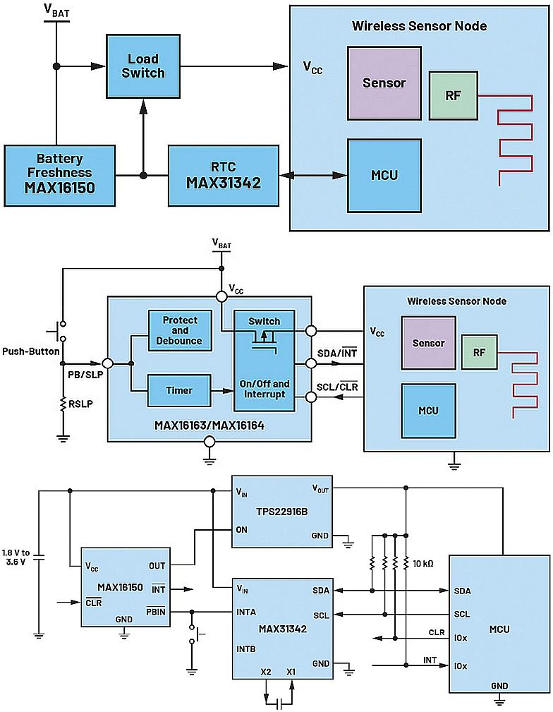
MAX16163/MAX16164 are Analog Devices’ nanopower controllers with on/off controllers and programmable sleep time. The devices integrate a power switch to gate an output, which provides up to 200 mA load current.
The MAX16162/MAX16163 can replace the conventional load switch, RTC, and battery freshness ICs to reduce BOM counts and costs. The wireless sensor node unit connects to the battery via the MAX16162/MAX16163. The sleep time can be programmed by the MCU or can be set using an external resistor from PB/SLP to the ground or using the I2C command from the MCU. The external push-button is used to exit the device’s ship mode.
The performance of both schemes depends on the duty cycle of the IoT application. In an application with a small duty cycle, the sleep current is a measure of how efficient the system is when the IoT device is running. The shutdown current is a measure of ship mode power consumption.
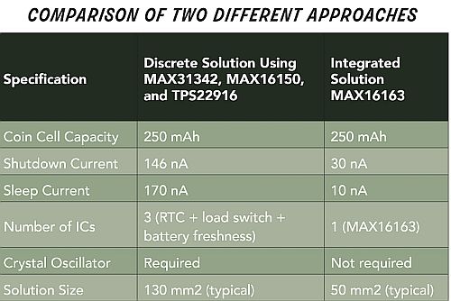
To demonstrate the mode of the solution, consider a system containing a MAX31342 RTC (which draws the industry’s smallest quiescent current), battery freshness seal 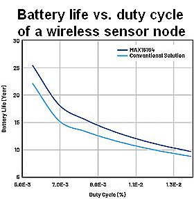 MAX16150, and tiny load switch TPS22916. The RTC is programmed using I2C communication that sets the sleep time of the IoT application. When the timer expires, the interrupt signal pulls down the PBIN pin of the MAX16150, which sets the OUT high and turns on the load switch. During the sleep time, only TPS22916, MAX31342, and MAX16150 consume power system power.
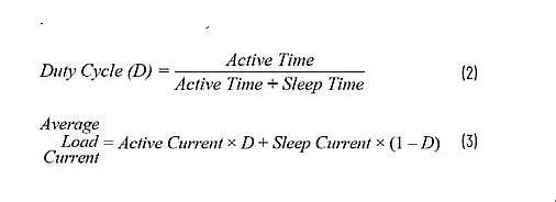
Suppose we compare the performance of the conventional vs improved approaches under fixed duty cycles using the MAX16163. The lifetime of the battery can be calculated using the average load current and battery capacity.

The average load current can be calculated using the duty cycle of the system.
 Active current is the system current when the wireless sensor node is active. To compare the two approaches, assume the system wakes up once every two hours, performs the specific task, and enters sleep mode after. The system active current is 5 mA. The battery life depends on the duty cycle of the operation.
The MAX16163 from ADI enables a design with a more precise control. It extends battery life by about 20% (for a typical 0.007% duty cycle operation) and reduces the device size to 60% of that required in a conventional approach.


Leave a Reply