
Brushless DC and stepper motors may get more attention than the classic brushed DC motor, but the latter may still be a better choice in some applications.
The attractiveness of brushed DC motors for some applications and the challenges of optimizing their performance has attracted vendors of special driver ICs which are well-suited for this situation. The key to getting superior performance from a brushed motor is to not use just a simple, steady-state DC supply of adjustable voltage.
Instead, it’s better to drive the motor with full voltage pulses and pulse-width modulation (PWM). Note that use of PWN is not limited solely to brushed DC motors; it is used for many other electronic functions where the objective is to modulate the drive signal power and so avoid problems associated with reducing the nominal voltage.
Use of PWM also helps avoid friction-based problems (mostly static friction, or stiction), common when a decrease in signal magnitude drives a mechanical load. In these cases, there isn’t enough drive power to cause the load to begin to move until the drive increase past a certain threshold; then, the load finally “breaks free” and jumps into motion rather than smoothly ramping.
Using PWM, however, complicates the specifics of modeling the motor performance. The equivalent circuit for the motor is simple when it is driven by a basic adjustable-voltage DC source (Figure 1).

However, as PWM drive is used and the motor speed increases, the model becomes a little more complicated (Figure 2).

When the motor is running at moderately high speed, the back EMF is comparable to the applied voltage, so a component representing the back EMF needs to be added to the equivalent circuit. The presence of back EMF and the resistor-inductor (RL) circuit in a brushed DC motor brings non-linearity to the PWM control. Both the PWM frequency and PWM duty cycle become significant for optimal output power. As the PWM frequency is increased beyond a threshold value, the PWM on and off time becomes less than the time required for the RL circuit to operate and the current to reach its steady-state. Hence, the current oscillates between two non-steady-state values, which gives rise to the current ripple.
ICs to the rescue
As is often the case, ICs which embed advanced hard-wired algorithms can compensate for and even optimize performance of a circuit, system, or load’s real-world idiosyncrasies, and this is the case for brushed DC motors. For example, the TB9053FTG and TB9054FTG from Toshiba Electronic Devices & Storage Corporation (Toshiba) are pulse-width-modulated (PWM) two-channel drivers for brushed dc motors (Figure 3). They are optimized for automotive applications such as throttle valve control, engine valves, retractable door mirrors, seat positioning, and door latches. (Who knew there were so many brushed motor opportunities in a car?)
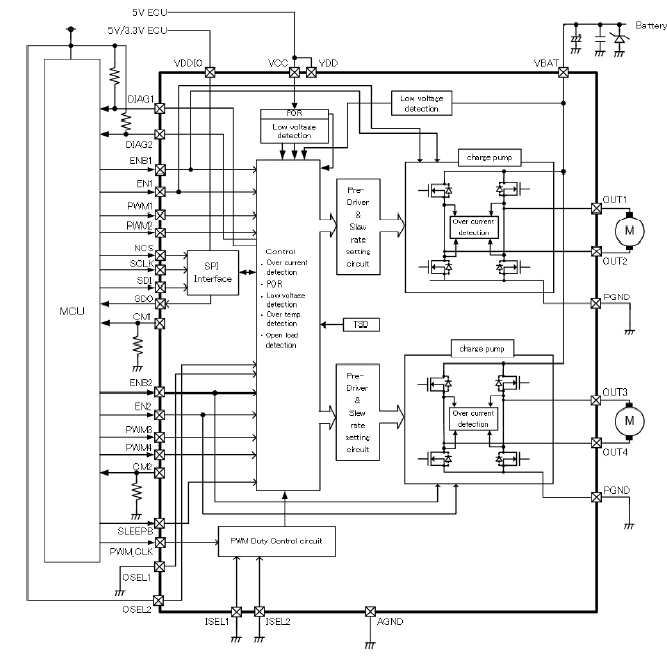
The monolithic silicon drivers can deliver up to 6.5 A (typical)/10 A (maximum) with on-resistance (RDS(ON)) of 142 mΩ at a junction temperature TJ of 25°C and battery voltage (VBAT) down to 8 V. Using the SPI interface of these drivers. The system microcontroller can control speed as well as set Forward, Reverse, Stop, and Brake modes. Speed also can be controlled directly by a PWM-based duty cycle. The ICs are pin-selectable for H-bridge or half-bridge mode.
As these ICs target automotive applications, built-in capabilities for monitoring, protection, and diagnostics are especially critical (some of which might even lead directly to the dreaded “check engine” light). Problem-detection features include those for overcurrent, overtemperature, VBAT undervoltage, and VCC undervoltage, among others, along with appropriate short-circuit and other protections. Other diagnostics include a power-supply fault-detection circuit, open-load detection during operational and non-operational modes, load shorts, and more. There’s also a diagnostic pin for each channel which, when used in conjunction with other pins, can report any specifics of the situation to the MCU when the various problems do occur.
Devices on the SPI bus can be connected in parallel or a daisy-chain configuration with the usual tradeoff between pin-count data-transfer rates. In the former case, a communication clock (SCLK), a data output (SDO), and a data input (SDI) are connected in parallel, while the external MCU (Master) assigns an independent chip-select signal to each driver to enable individual access (more MCU I/O ports are needed, but faster loading). In the daisy-chain mode, data from the MCU is clocked and propagates serially through all connected drivers, thus requiring far fewer MCU I/O pins but resulting in longer time to load data into the target driver IC.
Both drivers are in 40-small flat packages but of different types: there’s a QFN40 (quad-flat non-leaded) package for the TB9053FTG and VQFN40 (very thin QFN) for the TB9054FTG. The different packages result in slight differences in thermal and drive performance as well as physical-layout considerations.
These Toshiba ICs are just two of the many available smart brushed-motor driver ICs. Others include the broad Texas Instruments family of DRV8xxx drivers with a range of features, functions, channels, and power (current) levels.
Conclusion
Good engineers do not arbitrarily dismiss older solutions without good cause, nor do they easily succumb to “conventional wisdom” when ruling out some solutions. The brushed motor still has widespread applications beyond the highly specialized pump example cited or low-cost toys despite its apparent shortcomings. It is widely used in mass-market products, including automobiles with their harsh electrical and mechanical conditions. When paired with suitable drive ICs designed specifically for the brushed-motor attributes and applications, they remain a viable choice in many cases – as demonstrated by the fact that millions of them are sold annually for non-trivial, non-toy applications.
Related EE World Content
- Driving brushed and brushless DC motors
- Speed Controller for Brushed and Brushless DC Motors
- Brushed DC Motors in Industrial Versions
- Basics of motion-control profiles, Part 1: Context
- Basics of motion-control profiles, Part 2: Ramp profiles
- Basics of motion-control profiles, Part 3: Implementations
- Motor fundamentals and DC motors
References
Machine Design, “Controlling Brushed DC Motors Using PWM”
Medical Design Briefs, “Every Drop Counts: Designing Motors to Optimize Home and Ambulatory Infusion Pumps”
Portescap, “Miniature Motors Deliver Big Performance for Medical Analyzers”
Portescap, “Selecting Miniature Motors for your Medical Devices”
Portescap, “Brush DC Motor Basics”
Portescap, “Controlling Brushed DC Motors Using PWM – Optimal Frequency, Current Ripple and Life Considerations”
Toshiba, TB9053FTG and TB9054FTG Data Sheet
Leave a Reply