
DC motors are available in various electrical configurations and, except for brushless DC (BLDC) motors, are relatively simple devices. As a result, driving brushed DC motors is a relatively simple process. As shown below, BLDC motors require a more sophisticated approach. A “motor drive” is not even necessary with brushed dc (BDC) motors in some applications. All’s that’s needed is an on/off switch.
While it’s possible to vary the speed of a BDC motor using a simple voltage-divider approach, that’s inefficient and is rarely used. In most instances, some form of pulse-width-modulation (PWM) drive is used to control the current in the BDC motor windings and control the speed (and in some cases, the direction) of rotation. PWM control is far more efficient and can be implemented with relatively low-cost dedicated motor control ICs or simple microcontrollers (MCUs).
Basic BDC drive circuits
Low-side and high-side BDC motor drive circuits can be used to implement inexpensive one-direction speed control. In a low-side drive, shown below, the load is between the power rail and the N-channel MOSFET doing the switching. The low-side switches are often used for low power applications because they can be driven directly with an MCU’s output. The diode (D1) across the motor is used to prevent back electromagnetic flux (BEMF) voltage from harming the MOSFET. BEMB is generated when the motor is spinning. D1 prevents reverse current flow when the motor is turned off, and this diode must be large enough to handle that current flow. Resistors R1 and R2 are protection devices. R1 protects the controller from current spikes, and R2 ensures that the MOSFET turns off properly. In simple, cost-sensitive, low-power applications such as toys, this basic circuit is sufficient.

For larger BDC motors, a high-side drive, shown below, is generally preferred. A basic high-side drive uses P-type MOSFETs. However, N-type MOSFETs are preferred for switching heavy loads. The use of N-type MOSFETs in high-side drives requires the use of a charge pump or other device to pull the gate/base voltage above the source/emitter voltage. That complicates the design and makes it more expensive but potentially more efficient. It can also result in higher sensitivity to noise and electromagnetic interference. Components R1, R2, and D1 serve the same purposes as described above for a low-side BDC motor drive circuit.

Bidirectional drive circuits
An H bridge is built with four switches and can be used for bidirectional motor drive applications. For example, when the switches S1 and S4 (in the diagram below) are closed (and S2 and S3 are open), a positive voltage will be applied across the motor. By opening S1 and S4 switches and closing S2 and S3 switches, this voltage is reversed, allowing reverse operation of the motor. In addition, applying PWM drive techniques supports variable speed operation.

Switches S1 and S2 should never be closed simultaneously, as this would cause a short circuit on the input voltage source. The same applies to the switches S3 and S4. This condition is known as shoot-through.

The H-bridge arrangement is generally used to reverse the polarity/direction of the motor. Still, it can also be used to ‘brake’ the motor, where the motor is stopped rapidly, as the motor’s terminals are shorted, or to let the motor ‘free run’ to a stop, as the motor is effectively disconnected from the circuit.
Driving BLDC motors
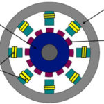
BLDC motors use electric switches to perform commutation and thus continuously rotate the motor. These electric switches are usually connected in an H-bridge structure for a single-phase BLDC motor (described in the previous section) and a three-phase bridge structure for a three-phase BLDC motor shown below. Usually, the high-side switches are controlled using PWM, which efficiently limits the startup current, control speed, and torque.

Brushless motor commutation can be implemented in software using an MCU or may be implemented using analog or digital circuits. Commutation with electronics instead of brushes allows for greater flexibility and capabilities not available with BDC motors, including speed limiting, “micro stepped” operation for slow and fine motion control, and a holding torque when stationary. Controller software can be customized to the specific motor used in the application, resulting in greater commutation efficiency.
Feedback mechanisms
While an ideal motor’s speed is proportional to the drive voltage or the PWM duty cycle, motors are non-ideal devices. Commutator wear, varying loads and heat, and other factors can affect the speed of a motor. Various feedback mechanisms can compensate for the non-ideal effects and improve the precision of the motor speed control. Sensor-based and sensorless feedback mechanisms can both be used.
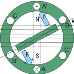
Sensor-based feedback systems generally employ optical encoders or hall-effect sensors. Optical encoders are mechanical systems where a slotted wheel is mounted on the motor shaft. On opposite sides of the slotted wheel are an LED and a phototransistor. As the shaft turns, the phototransistor turns on and off with the passing of the slots in the wheel, providing a measurement of motor rotation speed.
Hall-effect based systems also employ a rotary component attached to the motor shaft. The rotary component is a wheel with one or more magnets attached to the outer rim. A stationary hall-effect sensor is used to detect each magnet’s passing, generating a pulse of current and providing a measurement of the motor’s speed of rotation.
Sensorless feedback is based on BEMF voltage measurement. The BEMF voltage is proportional to the speed of the motor. In a typical application, a voltage divider is used to drop the BEMF voltage into a range from 0- to 5-volts. An analog-to-digital converter is used to generate a digital signal that measures the motor speed and is sent to the controller.
That concludes the DC motor FAQs in this series. Advancements in digital logic enable complex control algorithms and, combined with the declining cost of power semiconductors, enable the use of higher performance AC motors in a growing number of applications. The next two FAQs will consider AC motor types and applications and AC motor drives and controllers.
References
Brushed DC Motor Fundamentals, Microchip Technology
Brushed DC Motors and How to Drive Them, Diodes, Inc.
Brushless DC motor fundamentals, Monolithic Power Systems
H-Bridge, Wikipedia
Leave a Reply