• Skip to primary navigation
  • Skip to main content
  • Skip to primary sidebar
  • Skip to footer
  • Subscribe
  • Advertise

Power Electronic Tips

Power Electronic News, Editorial, Video and Resources

  • Products
    • Power Supplies
    • AC-DC
    • DC-DC
    • Battery Management
    • Capacitors
    • Magnetics
    • MOSFETS
    • Power Management
    • RF Power
    • Resistors
    • Transformers
    • Transistors
  • Applications
    • 5G
    • AI
    • Automotive
    • EV Engineering
    • LED Lighting
    • Industrial
    • IoT
    • Wireless
  • Learn
    • eBooks / Tech Tips
    • EE Training Days
    • FAQ
    • Learning Center
    • Tech Toolboxes
    • Webinars & Digital Events
  • Resources
    • Design Guide Library
    • Digital Issues
    • Engineering Diversity & Inclusion
    • LEAP Awards
    • Podcasts
    • White Papers
    • Design Fast
  • Video
    • EE Videos & Interviews
    • Teardown Videos
  • EE Forums
    • EDABoard.com
    • Electro-Tech-Online.com
  • Engineeering Training Days
  • Newsetter Subscription

Thermal challenges with high-power resistors

October 12, 2021 By Kory Schroeder

Shrinking component sizes have complicated the task of ensuring temperatures stay below their allowable maximum.

Kory Schroeder • Stackpole Electronics Inc.

Electronic components of all types continue to shrink in size. In response, resistor manufacturers are devising resistors with higher power ratings but which come in commonly used sizes. Of course, when more power gets dissipated in a smaller package, it is important to consider the impact on thermal issues.

Chip resistor technology is evolving rapidly. Materials used in the construction of the resistor greatly impact how quickly and efficiently the part deals with the thermal energy it generates. The amount of heat that a particular resistor can dissipate depends on the specific heat of its materials and is proportional to the mass of the material used. For example, metal alloy resistors, whether wire-wound or made with low resistance alloys for current sensing, will exhibit better thermal conduction and have more mass than similar resistors with film elements. Consequently, metal alloy resistors typically have higher power ratings.

2512-size package
A typical 50 mΩ chip resistor in a 2512-size package.
What is more interesting, however, is the recent improvements in rated power for chip resistors of a given size. If we assume a size 2512 chip resistor with a metal element, there are currently power rating options ranging from 1 to 3W. In some cases, manufacturers may add a heat sink to the body of the resistor or make it thicker to better handle the additional heat. But in most cases the resistive element and the part itself are largely identical for the 1-W and higher power versions. Given that the amount of heat a chip resistor can dissipate depends on both the materials used and the amount of material present, it seems illogical that the same part can be rated at both 1 and 3 W. The key factor to understand is how hot will the part get in the application and whether the part can withstand this level of heat.

hot spot temperature
Hot spot temperatures for chip resistors in a 2512-size package.
The nearby chart shows the hot-spot temperature of a 2512-size all-metal current-sense resistor. The 2512-size chip resistors, even dissipating 1 W of power, will generate enough heat to create PCB design and layout challenges. Most manufacturers recommend a hot spot/terminal temperature of between 105 and 125ºC depending on the element material. This is the combined temperature on any resistor due to power dissipated and ambient air. Film resistors will typically have recommended terminal temperatures at the lower end of the spectrum while metal-element resistors will typically tolerate higher temperatures. At 1 W, the resistor may see temperatures of 115ºC which is acceptable for robust metal- element sense resistors. However, the 1.5, 2, and 3-W-rated parts show hot spot temperatures well above 125ºC. This hot-spot data implies that thermal reduction techniques are necessary when these parts are used at the higher power ratings,.

Thermal reduction strategies vary widely in cost. Their effectiveness varies with the application and surroundings. Convection cooling from fans may be practical in some industrial applications but not in small consumer electronics. Other methods such as the use of larger solder pads, copper traces of a heavier weight, larger traces, vias through the PCB, and heat sinks are all candidates. Components that either absorb heat (transformers or large inductors) or that can’t tolerate it (certain semiconductors) must be kept away from resistors running at high power. This distancing may be tough to accomplish in designs that require small footprints. These problems may force the use of more robust semiconductors along with multiple heat reduction methods.

Similar design considerations are necessary when using downsized chip resistors. A standard 1206-size chip may work for thick-film devices requiring a quarter-watt power rating. However, high-power 0603-size chip resistors are now readily available. These reduce the overall space needed (including solder pads and traces) by 66% or more depending on manufacturer recommendations. The significance of this size savings depends on the total circuit area and other factors such as trace routing. But the size reduction can be dramatic when multiple parts are replaced in this manner.

hot-spot temperatures
Comparing hot-spot temperatures between quarter-watt 1206 and quarter-watt 0603-size resistors.
A similar relationship holds for the heat increase accompanying this size reduction. The nearby chart shows the net rise in hot-spot temperature is only around 10ºC. But suppose five such resistors are downsized. The aggregate thermal impact would typically be greater than five times the individual delta, especially if those resistors sit near each other. The co-heating from neighboring resistors makes it more difficult to dissipate heat. Ditto for heat absorbing components such as large wound transformers or toroidal inductors.

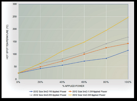
Depending on the PCB design, replacement of multiple chip resistors with smaller high-power versions can easily add 15 to 40 degrees of heat. For high density applications, even a reasonable combination of heat reduction methods may not be enough to deal with this kind of heat rise. Thus it may not be feasible to replace numerous resistors with smaller chip-packaged versions having higher power ratings.

All in all, current trends toward compact personal electronic devices make it desirable to use smaller components. Smaller components with higher power ratings are now readily available, but the net effect of close spacing makes it tough to keep surface-mount chip resistors below their 105 to 125ºC hot-spot temperature max. Keeping components below their maximum terminal temperature ensures stable operation and longer circuit lifetime.

You may also like:

  • talk of battery fires still smolders
    Talk of EV fires still smolders
  • charging
    Say goodbye to cross-country road trips
  • battery breakthrough fatigue
    Battery breakthrough fatigue
  • electrolytic caps
    Why electrolytic capacitors blow up
  • PoE
    Halt and catch fire: The perils of cheap PoE

Filed Under: FAQ, Featured, Power Components, Resistors Tagged With: stackpoleelectronics

Primary Sidebar

Featured Contributions

Robust design for Variable Frequency Drives and starters

Meeting demand for hidden wearables via Schottky rectifiers

The case for vehicle 48 V power systems

GaN reliability milestones break through the silicon ceiling

Developing power architecture to support autonomous transportation

More Featured Contributions

EE LEARNING CENTER

EE Learning Center

EE TECH TOOLBOX

“ee
Tech Toolbox: 5G Technology
This Tech Toolbox covers the basics of 5G technology plus a story about how engineers designed and built a prototype DSL router mostly from old cellphone parts. Download this first 5G/wired/wireless communications Tech Toolbox to learn more!

EE ENGINEERING TRAINING DAYS

engineering
“power
EXPAND YOUR KNOWLEDGE AND STAY CONNECTED
Get the latest info on technologies, tools and strategies for EE professionals.
“bills

RSS Current EDABoard.com discussions

  • Industrial Relay Board Design for Motorcycle Use
  • buffer conf
  • Voice extraction from a song
  • Step Up Push Pull Transformer design / construction
  • Is Silent Sound Spread Spectrum real?

RSS Current Electro-Tech-Online.com Discussions

  • UART Basic Before Writing Code
  • Impact of Tariffs on PCB Fab
  • Earbud wiring w/ mic
  • The Analog Gods Hate Me
  • Simple LED Analog Clock Idea

DesignFast

Component Selection Made Simple.

Try it Today
design fast globle

Footer

EE World Online Network

  • 5G Technology World
  • EE World Online
  • Engineers Garage
  • Analog IC Tips
  • Battery Power Tips
  • Connector Tips
  • DesignFast
  • EDA Board Forums
  • Electro Tech Online Forums
  • EV Engineering
  • Microcontroller Tips
  • Sensor Tips
  • Test and Measurement Tips

Power Electronic Tips

  • Subscribe to our newsletter
  • Advertise with us
  • Contact us
  • About us

Copyright © 2025 · WTWH Media LLC and its licensors. All rights reserved.
The material on this site may not be reproduced, distributed, transmitted, cached or otherwise used, except with the prior written permission of WTWH Media.

Privacy Policy