
Stepper motors can be configured for unipolar or bipolar drive; each approach has different performance attributes and tradeoffs.
Stepper motors are widely used, and, as with so many basic components, they are simple in some ways but also have multiple configurations and operating subtleties. For steppers (the “motor” part of the two-word term is often skipped), there are two widely used winding and drive configurations: unipolar and bipolar.
First, a note about terminology, as the terms unipolar or bipolar here have a different meaning than in most discussions about circuits in general and especially analog circuitry. Here, it does not relate to the stepper-motor application type of DC power rails. In those cases, “unipolar” means there is a positive supply voltage and ground but no negative supply, and the circuit operates solely from that single-ended supply. In contrast, a “bipolar” supply means the supply has both a positive and negative rail. The bipolar or split supply is needed because components such as op amps may require a dual supply to provide the full range of performance in some applications. However, these widely used meanings of unipolar and bipolar do not apply to stepper motors.
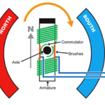
A stepper motor is a type of brushless DC motor built of connected coils referred to as “phases.” The motor’s rotor aligns with the coils due to the force created by the stator’s magnetic flux, which is generated by the current flowing in the phases (Figure 1).
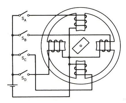
The drive current is directed to the next phase to generate incremental and fully controlled rotation. The sequence of driving that next phase results in rotational steps, which can add up to a partial, full, or continuous rotation motion needed and even reversed if desired.
Basic phase wiring arrangements
The construction of the coils and their wiring arrangement is broadly divided into unipolar and bipolar connection topology (Figure 2). Note that both unipolar and bipolar stepper motor configurations operate from a unipolar (single rail) power supply. Both configurations can be controlled to rotate in both directions from that single supply. Unipolar and bipolar configurations each have differences in drive circuitry, and performance attributes such as speed and torque, efficiency, and materials cost.
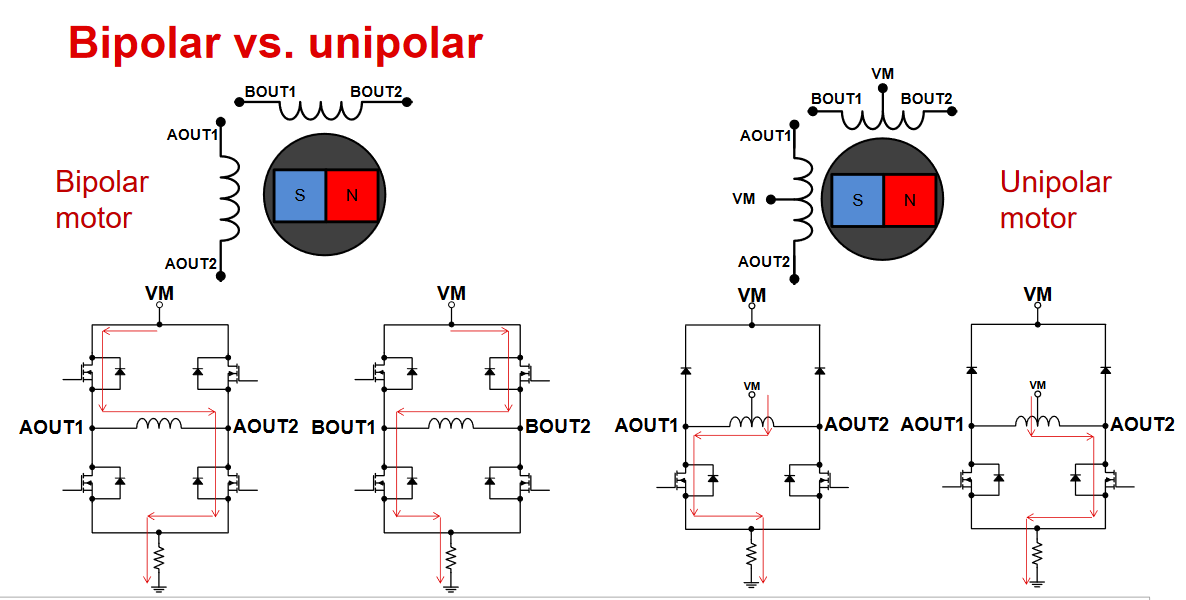
The unipolar stepper motor has one winding with a center tap per phase. Each section of the winding is switched via the commutation circuit to control the orientation of the magnetic field. In this way, the direction can be reversed without the need to switch the direction of the current, so reversal is possible despite the single-polarity supply. The wiring usually has three leads per phase and six leads for a regular two-phase stepper motor.
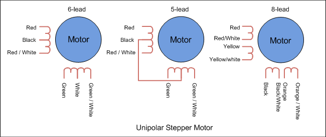
There are other arrangements for connecting the windings of unipolar motors, as the individual phase (coil) connections can be connected internally (Figure 3). Using such internal connections reduces connector wiring size and cost (it may seem trivial, but it may not be), and simplifies how the vendor winds the coil, but also lessen the possibility of drive-configuration flexibility; that may be an issue in some cases.
In contrast, the bipolar stepper motor has only a single winding per phase. Therefore, the driving circuit is more complicated to reverse the direction of current flow to the coil and reverse the magnetic field. The unipolar motor requires four transistors (MOSFETs) for full control in a half-bridge configuration, while the bipolar motor needs eight transistors arranged into two H-bridges for control. However, with modern ICs and power-control devices, the difference — especially for lower-power motors — is small and may be negligible.
The main difference between “unipolar” and “bipolar” stepper motors is the availability of the center-tap wire, which splits the full coils of the winding in half. This splitting can be done with one connection wire for the pair or two wires (one for the adjacent ends of each coil). By deleting the center tap, the unipolar connection becomes a bipolar-series connection.
[Motor-lead colors are somewhat standardized in the industry and are fully consistent within the product line of an individual vendor, so many wiring diagrams show color rather than numbering the leads. Some people find this useful and clear while others may find it confusing, but that’s the way it is.]
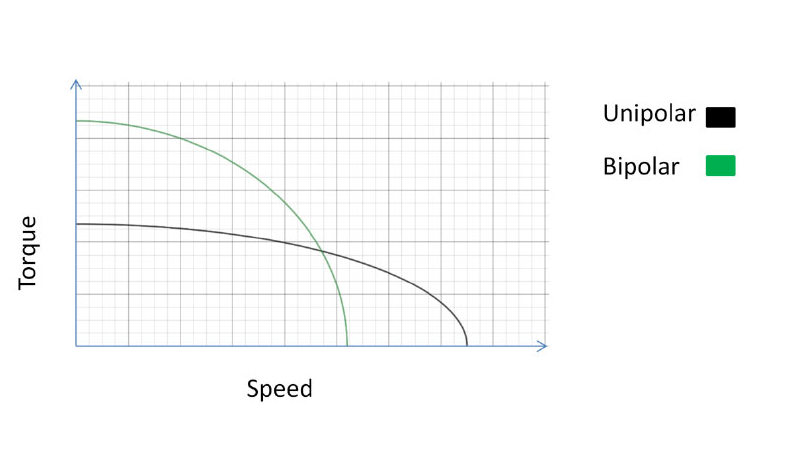
However, there is more to the situation than just choosing unipolar or bipolar configuration. It also means a change in the electrical characteristics of the windings inside the motor and thus affects voltage, resistance, and inductance, velocity, acceleration, and torque characteristics (Figure 4).
The next part of this article looks at some of the details and implications of the tradeoffs associated with different winding configurations.
Related EE World content
- Overcoming stepper motor design challenges in 3D printers
- Stepper motor driver IC simplifies low cost, power efficient designs with noiseless operation
- Basics of AC, DC, and EC electric motors (Part 2) — EC and stepper
- Thermal printers, Part 4: Components and circuitry
- Basics of motion-control profiles, Part 3: Implementations
- Basics of motion-control profiles, Part 2: Ramp profiles
- Basics of motion-control profiles, Part 1: Context
- Motor fundamentals and DC motors
- Basics of AC, DC, and EC electric motors, Part 1— AC and DC
External References
- Portescap (via Tech Briefs), “Bipolar and Unipolar Drives for Stepper Motors: A Comparison“
- Tech Explorations, “The difference between unipolar and bipolar stepper motors“
- Oriental Motor, “Wiring Basics: Unipolar vs Bipolar“
- Oriental Motor, “Unipolar/Bipolar Connections for 2-Phase Stepper Motors“
- Oyostepper, “Some differences between bipolar and unipolar stepper motor“
- Electrical4U, “Bipolar Stepper Motors: What is it?“
- Texas Instruments, “Drive unipolar stepper motors as bipolar stepper motors with a simple wiring reconfiguration“
- Texas Instruments, “Stepper Motor 1: Basics”
- Texas Instruments, “DRV8847 data sheet“
- Performance Motion Devices, “Magellan MC58113 Series Motion Control ICs“
- Performance Motion Devices, “Magellan Motion Control IC: MC58113 Electrical Specifications“
Leave a Reply