Rail splitters are usually associated with battery-powered devices, but that’s not always the case. There are several definitions of a “rail splitter,” sometimes referred to as a “virtual ground” or “pseudo ground.” The most common meaning is creating a new “0V” reference point, usually the mid-point Vin/2 of a single supply voltage such as a battery. In addition, while a simple voltage divider using two resistors can be used to create a virtual ground, the term rail splitter usually refers to using an active circuit to create a virtual ground.
Splitting a voltage source such as a battery can be handy in several instances. Sensors can require a bipolar supply voltage. Or a bipolar supply can improve the performance of some analog-to-digital converters (ADCs) and other ICs. Recently, active virtual grounds have been used to improve the performance of single-phase bridgeless power factor correction circuits. There are numerous options available to designers for creating a virtual ground, a few examples include:
- Unbuffered resistor divider networks to produce ±Vin/2 where the center point becomes a virtual ground. The addition of capacitors or a Zener diode can improve performance.
- Resistor divider networks buffered with an op-amp.
- Using various switch-mode power conversion topologies (buck, boost, buck/boost) to split a Vin rail into bipolar outputs, ±Vout, where Vout is not necessarily Vin/2.
- Using a voltage inversion circuit to produce a -Vout from a +Vin.
- Dedicated rail splitter ICs can be used to produce two outputs, ±Vin/2
- Inverting charge pump ICs can be used to produce ±Vin.
- Bidirectional switches can be inserted in the front-end of a single-phase bridgeless power factor correction circuit to create an “active virtual ground” that enables low common-mode voltage and low grid side differential-mode ripple current.
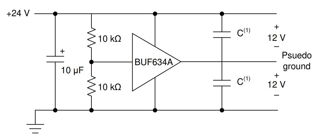
The BUF634A in the figure below creates a common ground buffered from the source; the buffer creates a more stable center point between the rails under load condition. While this is a stable and straightforward approach, these buffer amplifier circuits usually only handle a few milliamps and are relatively inefficient.
In the following figure, a switched-capacitor voltage inverter, ADM660, is configured as a “rail-splitter”. This configuration provides a bipolar, +/- 4.5V, dual-rail power supply from a 9V battery. After the power is applied, the flying capacitor, C1, is switched alternately across the storage capacitors, C2 and C3. This switching operation equalizes the voltages across those capacitors. It draws current from the battery as required to maintain the two output voltages to the virtual ground (GND node) equal to Vbatt/2. C2 and C3 usually have the same value.
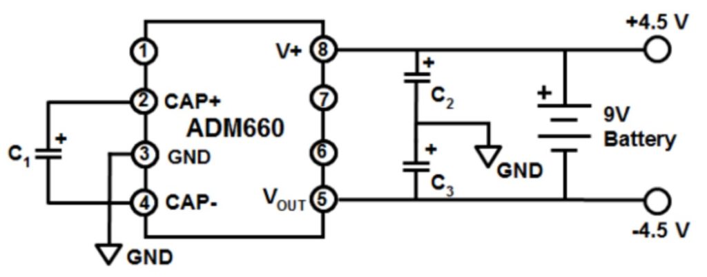
If the loads across +4.5 V and -4.5 V to ground are equal, the IC runs in a low current state and draws minimum current from the battery. To keep the battery centered around the virtual ground (GND), the flying capacitor has to supply only the difference due to unbalanced load currents. The voltage error and efficiency vary with the load current.
The switched capacitor approach provides better efficiency than an operational amplifier buffer circuit and much better regulation than a simple resistor divider network. But it suffers from increased output noise due to the high-frequency operation of the IC.
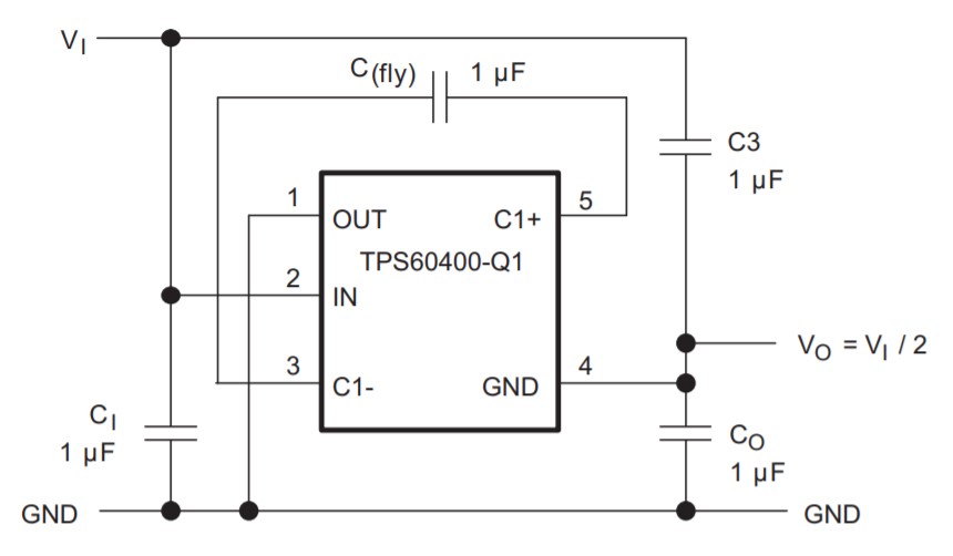
The second example of a high-efficiency switched capacitor rail splitter is shown below. The IC is in a SOT23-5 package, and the other components take up minimal board space. The operation is similar to the switched capacitor rail splitter shown above: After power is applied, the flying capacitor (C(fly)) connects alternately across the output capacitors C3 and CO. This equalizes the voltage on those capacitors and draws current from VI to VO as required to maintain the output at VI/2.
Switch-mode rail splitting
Inductor-based switching power converters can offer higher efficiencies, better accuracy, stability, and can handle higher currents compared with the approaches already discussed. In exchange for these performance improvements, inductive regulators are more complex, larger, and more expensive solutions. For example, the rail splitter below is based on a boost converter with a bipolar output capable of supplying a ±250mA output current with 90% efficiency for most input and output voltage configurations.
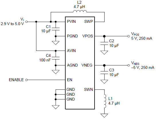
In addition, this approach is more flexible and does not necessarily require that Vin be equal to twice the voltage of the split rails. In the example above, ±5-V supply rails are obtained from input supply voltages in the range 2.9 V to 5 V, and the device has been optimized for use with regulated 3.3-V rails and single-cell Li-Ion batteries. Its output voltages are fixed at ±5 V and are not user-selectable. The EN pin controls the outputs, with a high logic level on the EN pin enabling both outputs and a low logic level disabling both outputs. Other designs can support user-selectable output voltages.
Active virtual ground for power factor correction
While most often associated with splitting battery voltages into two rails, the concept of a virtual ground has also been applied to single-phase bridgeless PFC (BPFC) topologies. The virtual ground PFC includes a conventional BPFC with an additional input section. The new input section is called an active virtual ground (AVG). It is used to change the input filter configuration to different LCL topologies depending on the grid voltage polarity using BPFC inductors. The new input section reduces grid-side differential mode (DM) current ripple and can employ smaller and lower inductance input chokes. In addition, the capacitor in the LCL filter clamps the voltage between the grid and the negative terminal of the dc bus, providing a low impedance path for high-frequency components, mitigating common-mode (CM) voltage concerns.
In practice, the AVG circuit can be connected in front of the BPFC. It provides low CM voltage, low grid-side DM ripple currents. It will maintain the low conduction loss advantages of the BPFC since the AVG is in parallel with the main current path, and it only manages the potentially troublesome high-frequency currents. In particular, CM voltages leading to leakage current issues can be a limitation for single-phase BPFCs in many applications.
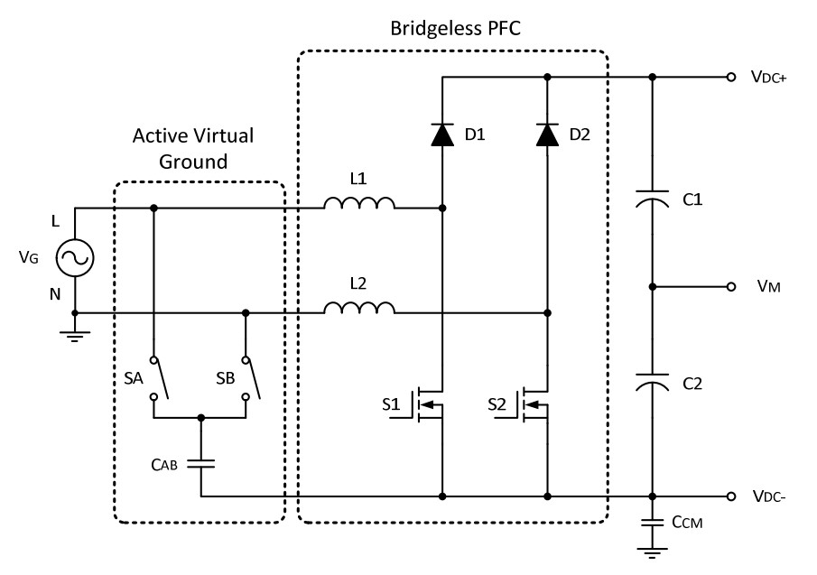
The added AVG circuit uses two bidirectional switches, SA and SB, in the figure above, connected to the line (L) and neutral (N) of the grid. While the bidirectional switches can be configured using various components such as IGBTs or MOSFETs for single-phase applications, back-to-back connected MOSFETs can provide a cost-effective and efficient option. The bidirectional switches are turned on alternately and synchronized with the line frequency. A capacitor (CAB) is coupled between the junction point of the bidirectional switches and the negative DC bus. It is used to clamp the potential difference between the ac power source and the converter ground. It provides a very low impedance path between the dc link and the system ground.
Summary
Rail splitters and virtual grounds are highly adaptive circuits and can take various forms, from passive resistor networks to complex switch-mode topologies. There are several tradeoffs in the different approaches regarding efficiency, voltage stability, current-handling capacity, cost, and solution size. Rail splitters were initially developed to provide dual voltage rails in battery-operated systems for components such as ADCs and sensors. More recently, the “active virtual ground” concept has been developed using bidirectional switches inserted in the front-end of a single-phase bridgeless power factor correction circuit to enable low common-mode voltages and low grid side differential-mode ripple currents.
References:
Active Virtual Ground – Bridgeless PFC Topology, University of Manitoba
Battery Voltage “Rail-Splitter,” Analog Devices
The top three ways to split a voltage rail to a bipolar supply, Texas Instruments
Voltage-inverter IC forms high-efficiency rail splitter, Maxim Integrated Products


Leave a Reply