
The two main types of AC motors are induction motors and synchronous motors. The induction motor (or asynchronous motor) always relies on a small difference in speed between the stator rotating magnetic field. The rotor shaft speed is called slip to induce rotor current in the rotor AC winding. As a result, the induction motor cannot produce torque near synchronous speed where induction (or slip) is not available.
In contrast, the synchronous motor does not rely on slip-induction for operation. It uses permanent magnets, projecting magnetic poles (usually made with steel laminations and called salient poles), or an independently excited rotor winding. The synchronous motor produces its rated torque at exactly synchronous speed.
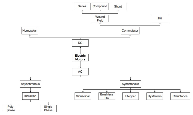
Induction motors
Most common single-phase AC motors use the squirrel-cage rotor, which will be found in virtually all domestic and light industrial alternating current motors. The motor takes its name from the shape of its rotor “windings”- a ring at either end of the rotor, with bars connecting the rings running the rotor’s length. It is typically cast aluminum or copper poured between the rotor’s iron laminates, and usually, only the end rings will be visible. Most of the rotor current will flow through the bars rather than the higher-resistance and usually varnished laminates. Very low voltages at very high currents are typical in the bars and end rings; high-efficiency motors will often use cast copper to reduce the rotor’s resistance.
Simple induction machines are directly connected to the grid. The typical torque-speed characteristic at constant stator frequency and terminal voltage is shown in the figure below. The synchronous speed corresponds to the rotating speed of the stator magnetic field. The machine produces no torque at synchronous speed because no current is induced in the rotor windings. If the rotor rotates at a lower speed than the stator field, the machine runs in motoring mode. Otherwise, the machine operates in generator mode. The maximum torque, which can be obtained at the motor shaft, is called pullout torque. The nominal torque is defined as half of the pullout torque. These machines usually operate in the linear region between the positive and the negative nominal torque, which is marked by the green line in the figure below.

An alternate design, called the wound rotor, is used when variable speed is required. In this case, the rotor has the same number of poles as the stator, and the windings are made of wire, connected to slip rings on the shaft. Carbon brushes connect the slip rings to a controller, such as a variable resistor that allows changing the motor’s slip rate. In certain high-power variable-speed wound rotor drives, the slip-frequency energy is captured, rectified, and returned to the power supply through an inverter. With bidirectionally controlled power, the wound rotor becomes an active participant in the energy conversion process, with the wound-rotor doubly fed configuration producing twice the power density.
Compared to squirrel cage rotors, wound rotor motors are expensive and require maintenance of the slip rings and brushes. They were still the standard form for variable speed control before the advent of compact power electronic devices. Solid-state inverters with variable-frequency drive can now be used for speed control, and wound rotor motors are becoming less common.
Large wound rotor induction motors (WRIM) are a well-established technology for industrial applications. In the cement and mining industries, high horsepower WRIMs are used on large grinding mills, where they have the advantage of controlled starting characteristics and adjustable speed capability. These motors are also used on large pumps in the water and waste industry.
A WRIM has a 3-phase wound stator that is usually connected directly to the power system. The rotor has a 3-phase winding, with the three terminals connected to separate slip rings, which were traditionally connected to a rheostat or resistor bank. The rheostat was used for starting and could be disconnected once the motor is up to speed. By changing rotor resistance with the rheostat, the motor speed can be changed. Solid-state drives are increasingly replacing rheostats for motor control in these applications.
Synchronous motors
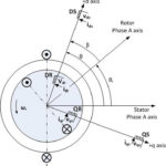
There are several variations on synchronous motor designs, including sinusoidal, reluctance, stepper, and hysteresis. The common denominator is that the rotation of the shaft is synchronized with the frequency of the supply current; the rotation period is exactly equal to an integral number of AC cycles. Synchronous motors contain multiphase AC electromagnets on the stator of the motor that create a magnetic field that rotates in time with the oscillations of the line current. The rotor with permanent magnets or electromagnets turns in step with the stator field at the same rate and provides the second synchronized rotating magnetic field of an AC motor. An asynchronous motor is termed doubly-fed if supplied with independently excited multiphase AC electromagnets on both the rotor and stator.
Small sinusoidal synchronous motors are commonly used in analog electric clocks, timers, and other devices where the correct time is required. In higher power industrial sizes, the synchronous motor provides two important functions: It is a highly efficient means of converting AC energy to work. And it can operate at leading or unity power factor and thereby provide a power-factor correction.
A reluctance motor is a type of electric motor that induces non-permanent magnetic poles on the ferromagnetic rotor. The rotor does not have any windings. It generates torque through magnetic reluctance. Reluctance motor subtypes include synchronous, variable, switched, and variable stepping. Reluctance motors can deliver high power density at a low cost, making them attractive for many applications. Disadvantages include high torque ripple (the difference between maximum and minimum torque during one revolution) when operated at low speed and noise due to torque ripple. Switched reluctance motors can be employed as very large stepping motors with a reduced pole count and generally are closed-loop commutated. Conventional stepper motors are a variation of brushless DC (BLDC) motor designs.
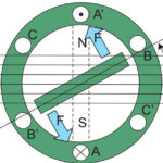
Hysteresis motors have a solid smooth cylindrical rotor, cast of a high coercivity magnetically “hard” cobalt steel. This material has a wide hysteresis loop (high coercivity), meaning once it is magnetized in a given direction, it requires a large reverse magnetic field to reverse the magnetization. The rotating stator field causes each small volume of the rotor to experience a reversing magnetic field. Because of hysteresis, the phase of the magnetization lags behind the phase of the applied field. The result of this is that the axis of the magnetic field induced in the rotor lags behind the axis of the stator field by a constant angle δ, producing torque as the rotor tries to “catch up” with the stator field.
An advantage of the hysteresis motor is that since the lag angle δ is independent of speed, it develops constant torque from startup to synchronous speed. Therefore, it is self-starting and doesn’t need an induction winding to start it. Hysteresis motors are manufactured in sub-fractional horsepower ratings, primarily as servomotors and timing motors. More expensive than the reluctance type, hysteresis motors are used where precise constant speed is required.
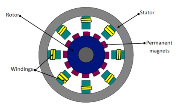
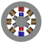
A permanent-magnet synchronous motor (PMSM) uses permanent magnets embedded in the steel rotor to create a constant magnetic field. The stator carries windings connected to an AC supply to produce a rotating magnetic field (asynchronous motor). At synchronous speed, the rotor poles lock to the rotating magnetic field. Permanent magnet synchronous motors are similar to BLDC motors.
PMSM versus BLDC performance
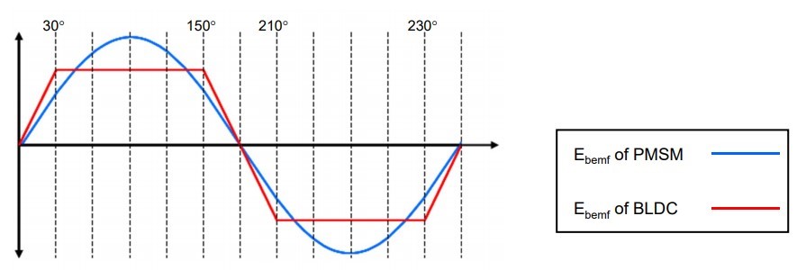
A PMSM motor can be seen as an AC counterpart of the BLDC motor. Like a BLDC, a PMSM has a permanent magnet rotor and a coil wound stator. The working of a PMSM motor is also quite similar to a BLDC motor. However, the difference lies in the waveform of the back EMF, which is sinusoidal in nature. This is because the coils are wound on the stator in a sinusoidal manner.
A PMSM requires AC power (sinusoidal in nature) to achieve the best performance. This type of drive current also reduces the noise produced by the motor. Advantages of PMSM motors:
- Higher efficiency than Brushless DC Motors
- No torque ripple when the motor is commutated
- Higher torque and better performance
- More reliable and less noisy, than other asynchronous motors
- High performance in both high and low speed of operation
- Low rotor inertia makes it easy to control
- Efficient dissipation of heat
- Reduced size of the motor
AC motor efficiency standards
International standard IEC/EN 60034-30 divides motor efficiency into five classes: IE1 to IE5. The National Electrical Manufacturers Association (NEMA) has a corresponding rating scale from ‘standard efficiency’ to ‘ultra-premium’ efficiency. The use of electronic drives is necessary to meet higher efficiency standards. Simple AC induction motors with electronic drives can meet IE3 and IE4 requirements, while PMSMs are needed to meet IE5 efficiency levels.
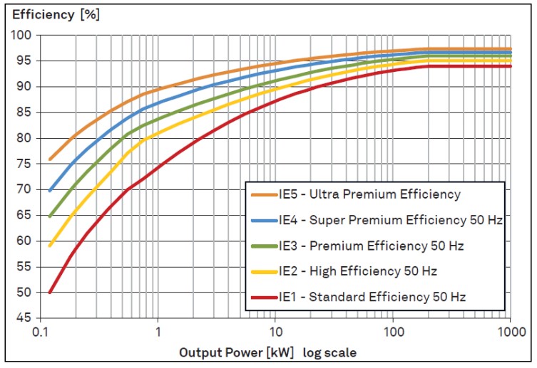
The difference between IE efficiency classes is larger for smaller motors. For example, for a 1kW motor, the increase in efficiency between IE1 and IE3 is about 13%. For a 10kW motor, the increase in efficiency between IE1 and IE3 is only about 6%
As noted above, electronic drives are necessary to meet higher efficiency standards. AC motor drives and controllers will be the focus of the fourth and final FAQ in this series.
References
Brushless DC Motor vs PMSM, Embitel
Motor handbook, Infineon Technologies
Leave a Reply