
Part 1 of this FAQ set the stage for a rudimentary understanding of FOC (field-oriented control) but did not delve into the math-heavy details. Part 2 now looks at some implementations, again without the underlying math.
Q: If a designer wants to implement FOC, does he or she have to pull together all the hardware components and the algorithms in firmware or software?
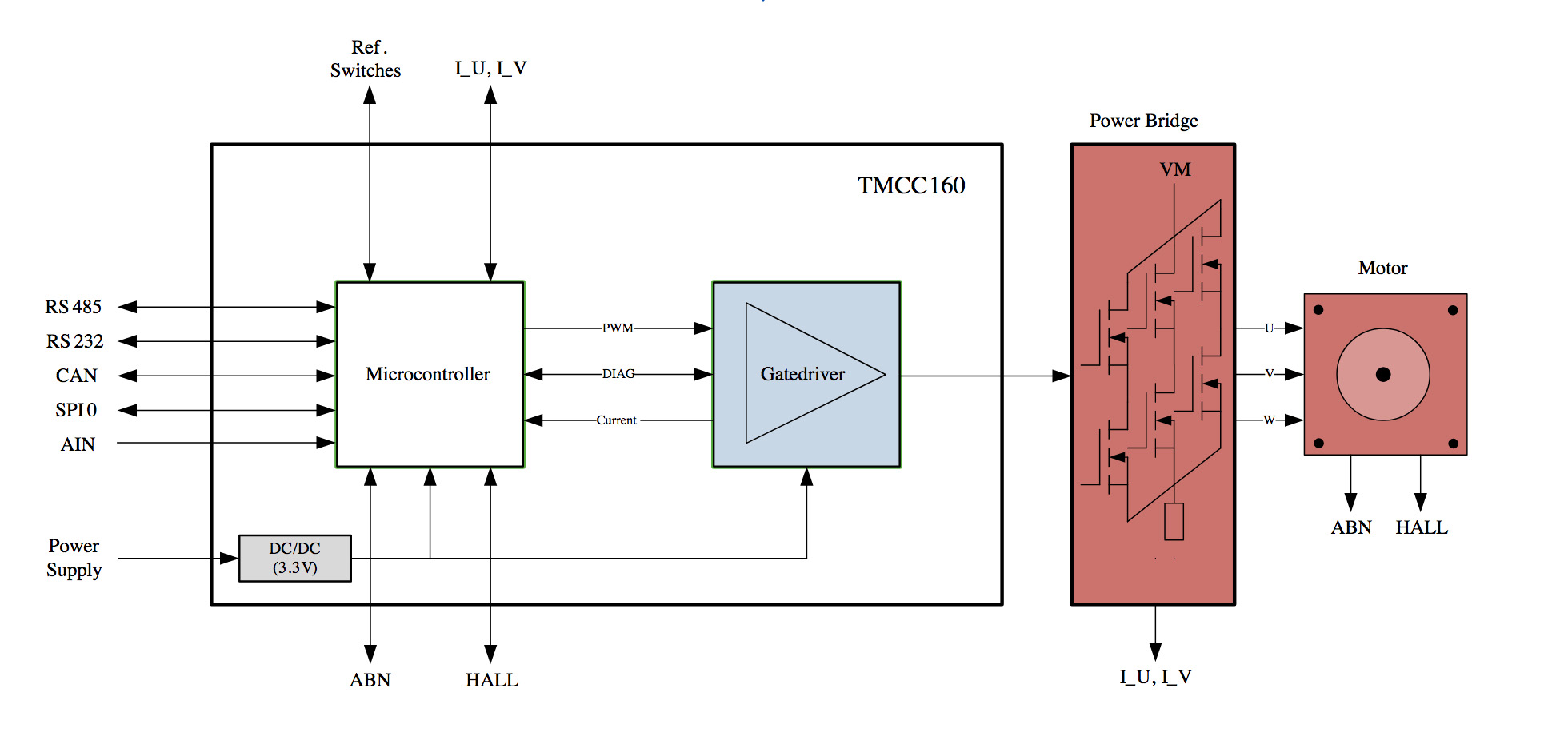
A: Of course not; many vendors offer complete FOC subsystems or systems on one or a few ICs. For example, TRINAMIC Motion Control GmbH & Co. KG, (Hamburg, Germany) offers their TMCC160 MotionCookie, an integrated microsystem which includes a 3-phase servo-gate driver suitable for up to 24 V and 1 A gate-drive current. The 12 mm ×x 17 mm IC (Figure 1), includes a complete servo controller software stack, while the integrated gate driver can support a wide range of N-channel power switches for 24 V motors. The IC works with incremental (quadrature) encoders or Hall signals for position feedback, with a field-oriented current control using pulse width modulation (PWM), a velocity control loop, and a position-control loop and ramp controllers, the software can define the complete servo controller stack. The incremental (quadrature) encoders or other sensor signals used for position feedback provide field-oriented current control with a velocity-control loop. It also offers a variety of interfaces such as RS-422/485, CAN, and SPI.
Q: What’s the situation with sensored versus sensorless FOC?
A: In traditional FOC, an angle sensor is needed to ensure that rotor flux is in phase with the rotor magnet. However, a basic, low-cost Hall-effect device which is often used for position sensing does not offer the needed precision, so a more-costly rotary-position encoder is often needed. This adds to the complexity of the hardware and cost of the sensor-based version, and also adds something else that can fail in use.
Q: So what is done?
A: Again, the details are too complex to fully describe here. Recall that the objective of the control loop is to measure the currents in the stator windings, compare them with the desired currents, and use the difference to generate an error signal; and then drive the currents to reduce or eliminate the error.
Briefly, in a sensorless design, by analyzing the relative phases of the three stator currents and voltages, it is possible to assess the situation in detail and calculate the solution to the closed-loop control vector. Note that Even though currents and voltages are scalars, there are three of each and they are located 120⁰ apart, so they form vector triplets. As such, their relative displacing (phase) can be used to adjust the timing (again, phase) of the stator currents.
Q: So a sensor is not needed?
A: That’s correct. If the system can “afford” the cost of digitizing each current and voltage at the required update rate (again, about 10 kHz in most cases) with adequate resolution (typically 18 bits) and perform the numerically intensive matrix math in real time to determine the constantly changing error and so generate a correcting signal, it can be done.
Q: Has anyone done it in a commercial product?
A: Yes, sensorless FOC has been used for between one and two decades in larger, more-costly systems, but it hasn’t been practical for lower-cost consumer products. Once again, however, advances in semiconductors are making what was once impractical now cost-, size- and power-effective for the mass markets.
Q: Can you give an example?
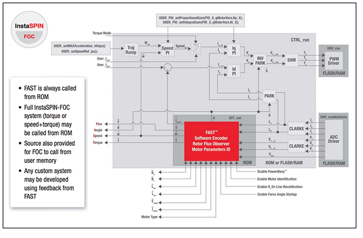
A: In the past few years, companies such as Texas Instruments developed high-performance devices with the needed computational power, along with support firmware and development tools. Their InstaSPIN-FOC motor control technology includes a software-based encoder algorithm (called a sensorless observer) for estimating flux, angle, speed and torque (known as the FAST quartet), embedded in the ROM of their Piccolo microcontrollers (Figure 2).
Q: If FOC is so good, why doesn’t everyone use it?
A: There are many reasons, but things are changing. First, it is still more costly for some situations, and the incremental benefit may be worthwhile. Second, it is complicated, and some designers who implement motor drives and controls don’t want to get involved with that level of advanced design expertise. Third, setting it up and optimizing the parameters for a given motor and load can be somewhat complicated.
But advances in smarter software (this does not require artificial intelligence) and development tools are changing that situation. Just as PID controllers used to require careful manual tuning before PID autotuning became quite good, FOC system suppliers have developed advanced auto-tuning which optimizes the FOC parameters to the desired priorities, as seen by the TI InstaSPIN motor control solutions (Figure).
This FAQ has looked at field oriented control, a brief description of how it works, its complexity, and how that complexity is being managed and reduced by highly integrated ICs and systems which also work with the needed firmware and tools. The references provide more comprehensive explanations, equations, and insight.
References — EE World
- EE World, “Rotary encoders, Part 2: magnetic encoders”
- EE World, “Basics of AC, DC, and EC electric motors (Part 2) — EC and stepper”
- EE World, “Single-IC intelligent motor control device is the right stuff for BLDC motor-based power tools”
- EE World, “Difference between synchronous and asynchronous (induction) motors”
- EE World, “What is Proportional (PID) Control and why is it used? (Part 1)”
References — others
- Texas Instruments, “Breakthrough InstaSPIN™-FOC motor control technology is here!”
- Texas Instruments, Application Report SPRACF3, “Sensorless-FOC With Flux-Weakening and MTPA for IPMSM Motor Drives”
- Texas Instruments, “TI InstaSPIN™ motor control solutions”
- Texas Instruments, “Field Orientated Control of 3-Phase AC-Motors”
- Trinamic, “Field Oriented Control”
- Roboteq, “Field Oriented Control (FOC) Made Ultra Simple”
- Controls, Drives, and Automation, “DTC or FOC – which is better?”
- Revolvy, “Vector control (motor)”
- International Journal of Engineering Trends and Technology (IJETT), “Comparison Between Direct and Indirect Field Oriented Control of Induction Motor”
- International Journal of Circuits, Systems and Signal Processing, “Performances comparative study of Field Oriented Control (FOC) and Direct Torque Control (DTC) of Dual Three Phase Induction Motor (DTPIM)”

Leave a Reply