
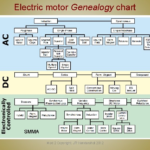
Field-oriented control, also known as vector control, is a calculation-intensive algorithm for motor control which is now practical due to advances in ICs; it offers improved efficiency along with superior control of torque and other performance parameters.
Motor control—and doing so accurately and efficiently—is a topic of great interest. Field-oriented control (FOC), sometimes called vector control, offers benefits for both those attributes. Although the principle is about 50 years old, it was impractical due to cost and computational requirements until the past few decades. That situation has changed, and it has now migrated “down” to markets and applications such as professional power tools, where it offers improved performance and battery life.
Q: What is FOC, in brief?
A: FOC is a technique used in variable-frequency drives to control the torque and the speed of three-phase AC electric motors, which includes 3-phase brushless DC (BLDC) and 2-phase stepper motors [Note that these motors are DC in the sense that their rail power is DC, but the power windings are switched, so they look like AC to the motor in many ways—it’s a matter of perspective.]. The objective of FOC is to direct the motor such that it achieves maximum torque at a given speed; it does this by ensuring that the rotor field is always lagging by 90° with respect to the stator under continually varying load conditions.
Q: How does FOC do this?
A: In a word, it’s complicated. In brief, it requires the measurement of motor currents and continuously transforming them into a coordinate system which rotates with the rotor of the machine. To make this reference-frame transformation work, it is necessary to measure the rotor position directly using speed or position sensors (sensored FOC) or infer it indirectly (called sensorless FOC). FOC does this and calculates the rotor flux angle at a kHz rate to then control the currents in the stator windings
Note that changing rotating frames of reference is not unusual, but it is challenging. When spacecraft are launched beyond the Earth’s orbit, we observe the craft from Earth, of course, but the navigation algorithms may prefer to use the sun as the “zero point” frame of reference and transform the Earth-observed data to Sun-centric data for navigation and guidance.
Q: This sound complicated; is it?
A: In a word, yes. The transformations require a considerable amount of matrix math and must be done in real time with the rotation of the rotor, with hundreds and even thousands of updates during each revolution.
Q: If it so complicated, why consider it?
A: If properly implemented, it provides superior dynamic response to load changes, better speed control, more accurate torque regulation, and quieter, lower-vibration operation—and reduces wasted power (heat, battery life).
Q: When did the FOC principle arise?
A: The origins of FOC date to the late 1960s and early 1970s, with work done by Siemens’ F. Blaschke in Germany, with a US patent application in 1971. The adoption of FOC was slow, as it requires all those calculations and well as other support electronics. However, as processor speeds and computing capabilities increased while cost and size decreased, it became more practical and cost-effective to use it.
Q: How does it work?
A: There are two ways to look at FOC: one involving electromagnetic theory and complicated equations, and the other with a more qualitative approach.
Q: Can we focus on using the second approach, please?
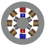
A: Absolutely, that makes sense here. First, let’s look at the sensored FOC approach. Using a BLDC motor as the example, the wires of all three phases are energized using a sinusoidal current that is 120° apart on each phase, and maximum torque occurs when the rotor’s magnet at 90° with respect to the stator field. In contrast, if the rotor magnet is at 0° and thus aligned with the stator field, there is a very strong pull directly outwards on the magnet, which represents wasted power as it produces no torque. Alignments between 0° and 90° produce some intermediate value of torque that is less than optimal versus applied power. But if the angular position of the rotor is known in real time, the voltages on the trio of phase windings can be controlled to maintain that 90° difference
Q: Then what happens?
A: While it may seem easy to control the voltages to the windings, the voltage and current to a target winding are not in phase (it’s a magnetic inductive load), while the magnetic field of interest is the result of current being driven into a coil, not voltage—however, that phase difference ci snot known in advance and constantly changes.
Q: So what does FOC do?
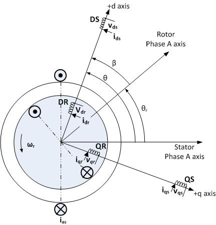
A: In FOC, the current is resolved into two perpendicular parts: the part which causes the desired perpendicular pull, called torque or quadrature current Iq, and one that causes the undesired outward pull, called flux or direct current Id. Once these constituent current components are determined, FOC adjusts these two components by adjusting the phase of the voltage so the direct current becomes zero and only the desired torque current remains (Figure 1).
Q: And then?
A: The current which is on the motor leads is AC and the field inside the stator is rotating 3-phase magnetic field, but the rotor—which is rotating along with this rotating field—sees a constant force. To get there, a pair of mathematical coordinate transforms called the Clarke transform and the Park transform combine the angle data with the current data to measure the quadrature current Iq and direct current Id , which are both slowly changing currents as seen from the rotor’s frame of reference.
Q: Given all this data and numbers, how does this translate to actual motor control?
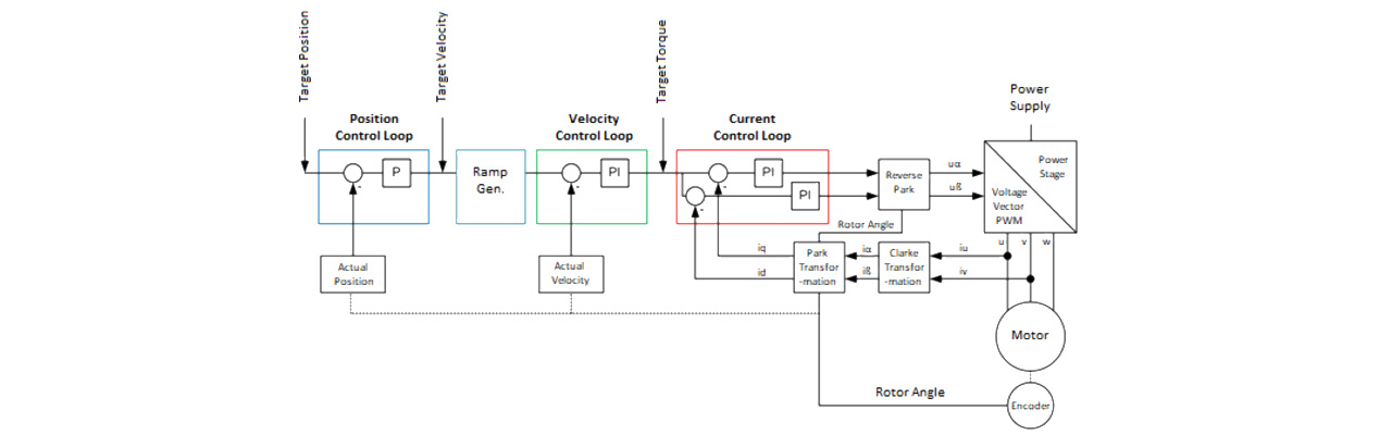
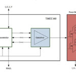
A: To do this, a pair of proportional-integral (PI) closed-loop feedback-control configurations are used to control both the phase and voltage to the coils to achieve the desired Iq and Id current values; usually, Id is driven towards zero to minimize wasted torque and maximize desired useful torque (Figure 2). The Park and Clarke transforms are inverted (which also demands an intense set of calculations) to generate the desired winding currents. This is all must be done at a high rate, easily reaching about 10 kHz for most rpm ranges, so the processing requirements are severe.
Q: This looks very complicated, but what are the operational details?
A: This is not the place for this level of detail, but the references provide additional insight.
Part 2 of this FAQ looks at FOC implementations including sensorless FOC, and available components.
References — EE World
- EE World, “Rotary encoders, Part 2: magnetic encoders”
- EE World, “Basics of AC, DC, and EC electric motors (Part 2) — EC and stepper”
- EE World, “Single-IC intelligent motor control device is the right stuff for BLDC motor-based power tools”
- EE World, “Difference between synchronous and asynchronous (induction) motors”
- EE World, “What is Proportional (PID) Control and why is it used? (Part 1)”
References — others
- Texas Instruments, “Breakthrough InstaSPIN™-FOC motor control technology is here!”
- Texas Instruments, Application Report SPRACF3, “Sensorless-FOC With Flux-Weakening and MTPA for IPMSM Motor Drives”
- Texas Instruments, “TI InstaSPIN™ motor control solutions”
- Texas Instruments, “Field Orientated Control of 3-Phase AC-Motors”
- Trinamic, “Field Oriented Control”
- Roboteq, “Field Oriented Control (FOC) Made Ultra Simple”
- Controls, Drives, and Automation, “DTC or FOC – which is better?”
- Revolvy, “Vector control (motor)”
- International Journal of Engineering Trends and Technology (IJETT), “Comparison Between Direct and Indirect Field Oriented Control of Induction Motor”
- International Journal of Circuits, Systems and Signal Processing, “Performances comparative study of Field Oriented Control (FOC) and Direct Torque Control (DTC) of Dual Three Phase Induction Motor (DTPIM)”
Leave a Reply