
A few best practices for handling transients and over-currents help make electronic drivetrains more reliable.
James Colby • Littelfuse, Inc.
Automotive market analysts predict that by 2025, high-end vehicles will contain more than $6,000 in electronic components. Most of these advanced electronics will be in the growing number of electric vehicles (EVs). To ensure robust, reliable, and safe performance, the vehicle electronics must be protected from current overloads, electrostatic discharge (ESD), and transient overloads. The battery pack is the source of the electric vehicle power and a critical, high-cost component of the vehicle.
EV batteries contain a lot of energy. These battery packs primarily contain large quantities of 4.2-V lithium-ion battery cells, generally operate in the 400 – 500-V range. A battery pack will include approximately 20 modules of lithium-ion cells in parallel-series combinations. Each manufacturer has its own proprietary module and battery pack design with capacities ranging from 35 to 100 kWH.
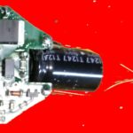
With 400–500-V battery packs holding kilowatt-hours of energy, safety is a major concern. For example, a short circuit in one battery component can draw significant power and substantially raise the battery temperature. Here, properly sized current interruption devices and transient overload protection are essential for avoiding catastrophic destruction or damage to the vehicle electronics and potential harm to the vehicle occupants.
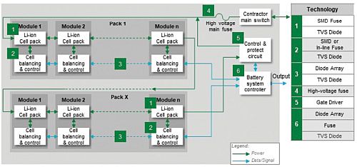
The typical EV energy storage system consists of the battery pack, the high-power current interrupt elements, the battery control circuitry, and the communication circuitry that transmits the status of the battery to the main vehicle processor.
It’s considered best practice to fuse each sense line of the cells for over-current protection. We suggest a fast-acting fuse for quick response to an over-current. Look for surface-mount fuses to consume minimal space on the module PC board. Also, look for AEC-Q-qualified components that meet automotive ruggedness standards and operate over a

temperature range of -55 to 125°C. To protect the cell pack from system-induced transients, ESD, and other types of transients, we recommend a transient voltage suppressor (TVS) diode. Surface-mount models can absorb up to 1,500 W of transient peak pulse power or up to 200 A of surge current. They also safely withstand an ESD strike of up to 30 kV. Look for versions that have AEC-Q101 automotive-grade qualifications.
We also recommend the design include over-current and transient voltage protection for the cell balancing and control circuit. This practice ensures all lithium-ion cells contribute approximately equally to powering the load. A fuse and a TVS diode are warranted.
In addition, the communication bus that links modules together should have ESD protection. ESD can be introduced during the assembly process and could create “walking wounded” components or outright catastrophic failures. We recommend a bi-directional ESD diode with ultra-fast response to clamp transients.

The whole battery pack assembly should have a fuse to protect against current overloads. Because the battery operates above 400 V, we recommend a time-delay fuse with a voltage rating exceeding the battery output voltage and able to carry the appropriate current capacity. In addition, protection components should be qualified to automotive reliability standards (ISO-8820, AEC-Q, etc.).
A control and protect circuit (C&PC) operates the contactor main switch and feeds its status to the battery system controller. The C&PC must operate fast. The circuit typically contains power MOSFETs to open the contactor; and, the MOSFET must switch quickly. We recommend a gate driver chip specifically designed to control MOSFETs. Gate drivers can exhibit rise times under 10 nsec and have high immunity to latch-up conditions. They ensure the MOSFETs operate efficiently.
The battery system controller feeds data on the battery packs to the main vehicle microprocessors. It requires current overload and transient voltage protection similar to that for the other circuit blocks. This circuit contains the CAN interface. Data line integrity is critical for uncorrupted data transmission. We suggest these lines be protected with ESD diodes. Fortunately, one component can protect the high and low lines.
Protecting battery modules

We have discussed a master fuse with a high voltage rating on the output of the module. Each individual cell should be fused as well. Low-voltage fuses can serve this purpose. Each module has its own microprocessor to monitor cell status and report it to master controllers. Thus, the wired Interface should use TVS diode arrays to protect the CAN data lines.
The battery distribution unit supplies the battery voltage to the various vehicle loads. We suggest a topology of high-voltage fuses and high-voltage/high-current contactors to protect individual loads from current overloads and to isolate each load from all others. This practice protects each load from a failure in any other load. In addition, consider adding contactors to provide a primary level of protection from the battery pack. The main contactors disconnect the battery from the various loads and the electric drivetrain. The pre-charge contactor (paired with a resistor) provides a path to initially charge the dc link capacitors to 90% of the battery voltage. This contactor-resistor combination protects the capacitors from the high inrush current that arises when the power to the pack is initially applied.

Despite judicious placement of protection components, the battery pack may develop an internal short or be subjected to an external one. How can the damage be contained? Consider including one last line of defense: a hybrid protection and disconnect module. The solution combines current sensing, a fuse, and an ignition system designed to ensure the battery disconnects from the load. The ignition system ensures a fast response of as little as 1 msec, and it punches a section out of the main battery busbar to guarantee the circuit opens and any arcing is extinguished. One self-contained module provides high interrupting-current capability with fast detection and response. The loads are protected from the short circuit current overload. This new technology minimizes damage to the battery.
In a nutshell, the complexity of the electric vehicle battery pack architecture points to the necessity for multiple levels of circuit protection. At the module level, the module as a whole and the individual cells require protection from over-current and overloads. The monitoring and control electronics should be fortified with transient voltage protection. The CAN data lines should have ESD and voltage transient protection to ensure undisrupted communication between the battery pack and the main vehicle microprocessors. Incorporating these protection topologies can help to eliminate the occurrence of a battery pack failure.
REFERENCES
Littelfuse Automotive Electronics Applications Guide
Automotive Electronics Council (AEC) Standards


Leave a Reply