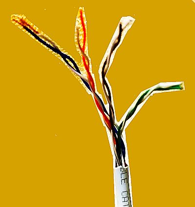
Look at just about any kind of network connection today and you’ll find Cat 5e cable. It’s been the most widely used network cable since 2001 and handles signals up to 100 MHz. So you find Cat 5e handling 10BASE-T, 100BASE-TX,

and 1000BASE-T Ethernet networks. But the actual power levels that Cat 5e sees when used in these kinds of networking applications is relatively low, on the order of a few hundred milliwatts.
However, Cat 5e is now also used in Power-over-Ethernet applications where it must handle significantly more power than in ordinary networking. In contrast to ordinary Ethernet signals having power in the range of hundreds of milliwatts, the latest power-over-Ethernet standard, called Hi PoE (802.3bt Type 4), allows for delivering between 90 and 100 W through Cat 5e cable to a load. The operating voltage for this mode of operation is 50 Vdc. That implies that the Cat 5e cable is carrying a little less than two amps of current when it operates in a hi PoE environment.
Now you might wonder whether a cable originally designed to carry power levels measuring in the hundreds of milliwatts can safely work in an environment characterized by two amps of dc current and loads dissipating 90 W.

If you examine the cable design specifications, they look fine on paper. Cat 5e cables usually run between 24 and 26 AWG, while Cat6, and Cat6A usually run between 22 and 26 AWG. Smaller AWG numbers mean larger wire diameters and thus less wire resistance. The wire in Cat6 and Cat6a patch cables run slightly thicker than their Cat5E counterparts.
That means the AWG 26 wire in a Cat 5e cable should have a resistance of 0.041 Ω per foot. AWG 26 wire is rated to be able to carry 2.2 A maximum. Because Hi PoE divides its 100 W among the four twisted pairs in the network cable, that means any one AWG wire in a Cat 5e cable should be carrying a half-amp at most.
The margin is a bit smaller in one of the newest types of Ethernet cables called Slim Run Patch Cables. These generally contain 28 AWG wire but there are versions available on Amazon with 30 AWG. Use of smaller twisted pair wires lets these cords be at least 25% smaller in diameter than standard Cat5e, Cat6, and Cat6a cable, but the higher AWG limits the length of the cable. The current-carrying capacity of AWG 28 and 30 wire is 1.4 and 0.86 A respectively.
 We should also point out that PoE equipment employs current limiting to protect PSE (power sourcing equipment) from overload and to quickly disable malfunctioning PDs (power devices). The current drawn on each enabled port is continuously monitored, and power is disconnected if it rises beyond an allowed setable limit. However, this safety feature may not prevent a network cable from heating up and perhaps melting until there is a short. It also doesn’t help much if a cable fails open.
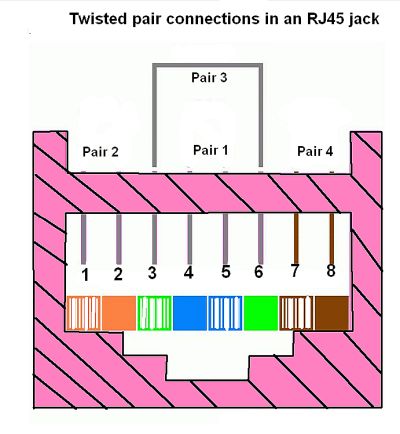
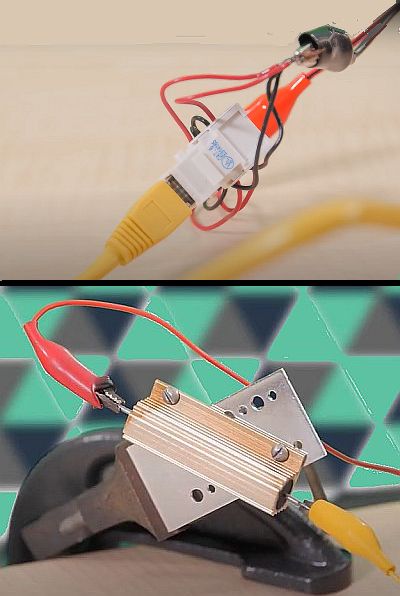
To check things out for ourselves, we put ordinary Cat 5e cables that came with some consumer electronics into a simulated Hi PoE scenario. We assembled two RJ45 sockets and wired them to route power through the cable as defined by Hi PoE, with each of the four twisted pairs in the cable sharing the dc load. We then connected one end of the cable to a 50-V power supply and the other end to a load resistor that would draw close to the two-amp maximum involved with Hi PoE. Then we just waited and checked the temperature of the cable in various spots over the course of the test, paying particular attention to bends in the cable where there could conceivably be some compromise to the cable conductors.

Though this was an informal test, we figured any obvious cable problems were likely to show themselves after a few hours of handling a Hi PoE load close to the maximum spec. We’re happy to report that absolutely nothing happened. We checked all along the cables we used with a spot thermometer numerous times. We never saw even a one-degree temperature rise in our cables, even where they were bent, and even after a couple of hours of handling the max Hi PoE power level.
All in all, we’re pretty sure that problems due to poor cable construction would cause a temperature rise sooner rather than later, so we think it’s probably OK to put Hi PoE power levels through ordinary Cat 5e cable.
That said, we should point out this wasn’t an exhaustive test. We only ran our simulations for a few hours, not for days or weeks. And testing took place at room temperature whereas the maximum operating temperature for Cat 5e cable is 167°F. Further, our test setup divided the dc current through the cable evenly among the four twisted pair. It is possible to envision Hi PoE scenarios where current doesn’t divide evenly, potentially exceeding the 2.2-A limit of any one twisted pair. The situation would of course be worse for Slim Run Patch Cables.


Very helpful, thanks!