Part 1 of this FAQ explored the basics of the optocoupler. This part looks at key parameters and some application examples.
Q: What are the primary factors used when assessing an optocoupler?
A: While there are many important factors, there are several which are noteworthy: isolation, current-transfer ratio (CTR), linearity (for analog use), and speed.
Q: How much isolation can an optocoupler provide?
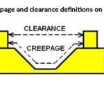
A: It varies with the device, but typical isolation is >1000 V, and >2000 V is available. Isolation is a function of physical input/output separation (especially creepage and clearance dimensions) and the material used, and defined largely by industry and regulatory standards such as IEC 60601-01 or UL 1577. While many applications only need modest isolation, on the order of tens of volts, there are many which do need hundred and thousands of volts.
There are regulatory standards to which optocouplers can be certified, thus allowing their use in safety-critical designs such as separating high-voltage and low-voltage circuit functions; if an approved device is used, many (but not all) of the end-product tests and documents for final approval are not needed.
Q: What is current-transfer ratio matter and why does it matter?
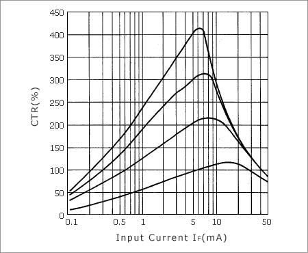
A: In simple terms, CTR indicates the efficiency of the optocoupler. If CTR is low, the input side will need more current drive to the LED in order to create sufficient current at the phototransistor for the output load. Higher CTR also provides some input/output margin as the LED ages. CTR ranges from about 50% to as high as 400%, Figure 1 (remember, the optocoupler is an active device and has gain due to the beta of the phototransistor. Also note that CTR is not a constant but is a function of the input LED current.
Q: What about optocoupler linearity?
A: Since the phototransistor is a transistor, if it is properly biased and operated in its linear range, it can support a linear input/output transfer function, unless it is in cutoff or saturation regions. Optocoupler designed for SSR applications are designed and biased so as to be non-linear, but achieving good linearity with an optocoupler is not difficult; for this reason, they are viable as the feedback element in an isolated voltage regular (power supply).
Q: What speed/bandwidth and response time an optoisolator achieve?
A: Many applications are at mostly low bandwidth and speed, such a separating grounds or measuring voltages across batteries, so speed is not an issue. However, more speed may be needed for isolating digital-datalink signals, depending on the specifics; as speeds range from slow (I2C, SPi, RS-232/423), to modest (CAN bus), to faster (USB 3.0), and even to Ethernet (tens of Mbps).
Basic optocouplers typically have bandwidth over 10 MHz, and those designed for speed can support date rates of 50, 100, and even 200 Mbps. In the time domain, response time between applying a current pulse and seeing an output is on the order of microseconds, but this is depending on the device, load resistance, temperature, and other factors.
Q: What are some representative application connections for optocouplers and the isolation they provide?
A: Among the many applications — some for convenience, and some mandatory — are these:
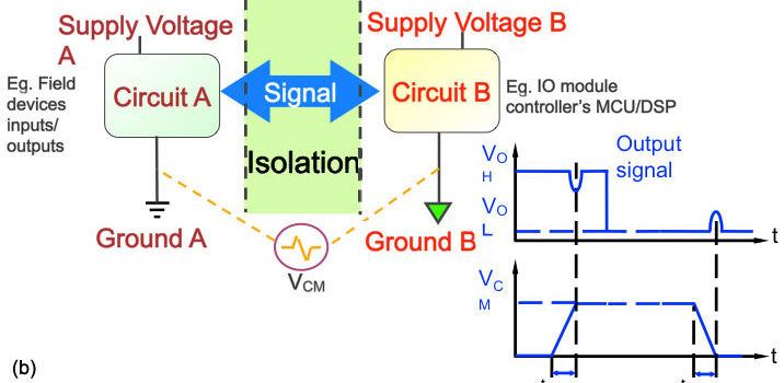
—eliminating common-mode voltage due to ground-potential differences, Figure 2:
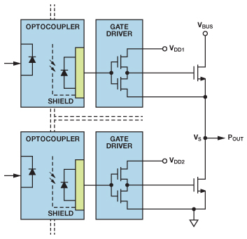
—for level shifting and ground isolation in totem-pole (or H bridge) drivers, Figure 3:
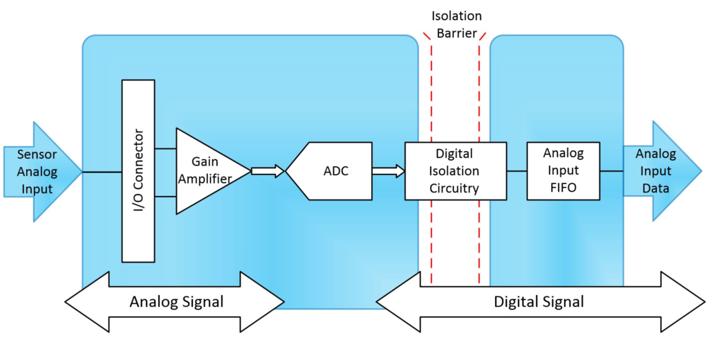
—for sensor interfaces, especially where the sensor is not grounded, Figure 4:
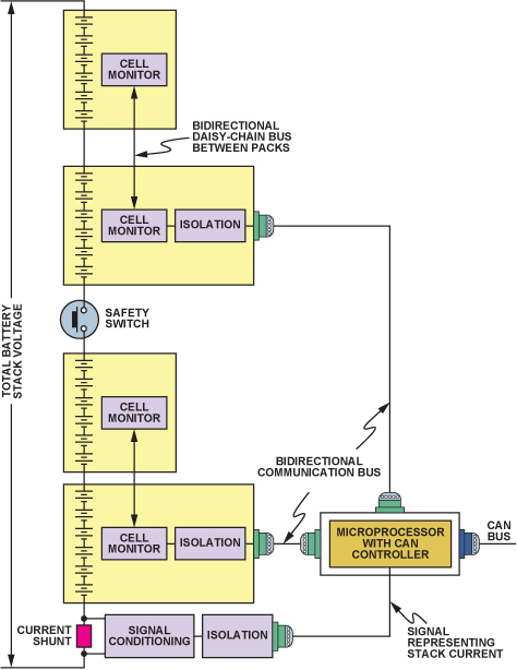
—for measuring the voltage across a single or group of series-connected batteries, where the battery or set being measured is at very high potential with respect to system ground, Figure 5:
Q: Since an LED is a DC-current device, how is an optocoupler used with AC signals, such as power lines and lamp (incandescent, LED, CFL) dimmers?
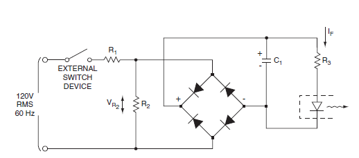
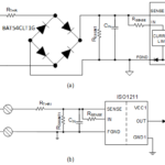
A: A basic full-wave rectifier and modest filtering can be used to drive the LED of the optocoupler, with appropriate current scaling via a basic resistor or even a real current source, Figure 6:
Q: Are there many vendors of optocouplers?
A: Yes, there are dozens; some are broad-line vendors who offer unrelated devices, others specialize in optocouplers, and some even offer “competing” isolation technologies as well.
References
- EE World, Power Electronic Tips, “Solenoids and relays, Part 1”
- EE World, Power Electronic Tips, “Solenoids and relays, Part 2”
- EE World, “Galvanic isolation for electric vehicle systems”
- EE World, “Electrical isolation technology at Silicon Labs”
- EE World, “Why isolated digital inputs are replacing optocouplers in up to 300V systems”
- EE World, “Selecting an optocoupler to isolate a PWM”
- EE World, “How should grounds and commons be connected to each other?”
- EE World, “Flashovers and clearance in electronic equipment”
- Renasas Electronics Corp., “Current Transfer Ratio (CTR) and Response Time of Photocouplers/Optocouplers”
- Fairchild/ON Semiconductor, Application Note AN-3001, “Optocoupler Input Drive Circuits”
- Vishay Semiconductors, Application Note 01, “Guidelines for Reading an Optocoupler Datasheet”
- Vishay Semiconductors, Application Note 02, “Optocouplers and Solid-State Relays: Application Examples”
- California Eastern Laboratories, “Application Based Optocoupler Design Guide”
- California Eastern Laboratories, “Optocouplers Product Selection Guide”
- Kynix Semiconductor Electronic Blog, “How Optocoupler Works and the Optocoupler Basics”
- Elprocus, “Opto Couplers – Types & Applications”




Leave a Reply