
Light-emitting diodes – often referred to simply as LEDs – have become the preferred light source in many applications, whether for area illumination, spotlighting, signage, or backlighting. While there are some applications which prefer to use a smaller number of very high-power LEDs, many applications benefit from, or must use, a larger number of lower-to-moderate-power LEDs in terms of lighting, cost, consistency, and heat dissipation. Part 1 of this FAQ will look at how these LED arrays can be arranged and the associated tradeoffs, while Part 2 will look at specifics of proving the power – the voltage and the current – that these arrays require. Of course, the array arrangements and the power needs are closely related, but we’ll separate them to the extent possible)
Q: What is the basic situation of a single LED?
A: While an LED can be driven by either a properly sized voltage or current source, the LED itself is a current load. It has a constant voltage drop (typically around 1.5 to 2.0 V but may be higher), and its output intensity varies with current.
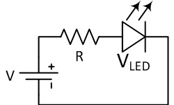
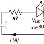
Q: So I can drive an LED with just a voltage source?A: Yes, but you need one more component: a current-limiting resistor, Figure 1. It will work acceptably when using an LED as a basic on/off indicator, for example. In most cases, though, this is not a good approach: it has poor regulation and does not take into account how the LED performance shifts with self-heating and temperature; it wastes power in the current-limiting (voltage-dropping) resistor; and LED current and therefore the intensity will be a function of the source voltage so that, too, needs to be regulated.
Q: What’s the alternative?
A: In most cases, it’s better to use a true current source to drive the LED. A typical LED requires 20-30 mA for optimum intensity, but high-intensity LEDs can go as high as 50-100 mA, and some are even higher. Also, with a constant-current source, the driver keeps the current fixed even as the voltage drop across the LED changes with temperature, thus preventing thermal runaway from inadvertently overdriving the LED.
Q: OK, that’s for one LED—what about multiple LEDs?
A: Here’s where things get both interesting and complicated. Multiple LEDs are often needed to provide the total needed amount of illumination, to cover a broader area more evenly, for redundancy, or due to the inherent nature of the application (such as signage letters and images). Designers have many ways to organize these multiple LEDs electrically.
Q: How can the LEDs be arranged?
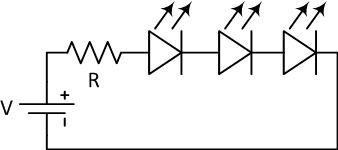
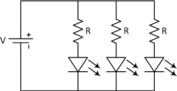
A: The two obvious ways. In the series interconnect, they are in a single string with the anode of one LED connected to the cathode of the next LED, Figure 2. Or, they can be in connected in parallel, with all LED their cathode ends connected, Figure 3.
Q: What are the issues associated with simple serial arrangement?
A: Serial seems simple enough, and it is. A single source supplies the serial string at the target current. While a short circuit in any single LED will not affect the operation of the remaining LEDs, an open-circuit failure (the most common LED failure mode) means the entire string of LEDs goes dark.
[Note that there are special devices available which can be placed in parallel with each LED and appear as a high impedance until the LED goes “open,” at which point they become a short-circuit and allow current to flow and thus the string to remain lit. These are a sort of functional complement to a conventional fuse.]
Second, in a series arrangement, the amount of current hat the supply must deliver is the same regardless of the number of diodes, but there is no “something for nothing” here. Though the current stays constant, the sum of the diode-voltage drops means that the supply must deliver this current at ever-higher voltages, called the compliance voltage. If there are 10 LEDs and each has a 1.5 V (nominal) drop, the compliance voltage is 15 V, which is easy to provide. But as the number of LEDs increases, the compliance voltage reaches into many tens of volts, which is more difficult to source and also gets into regulatory areas of safe-voltage levels.
Q: What about parallel connection?
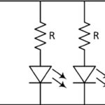
A: In a parallel connection, each diode sees the same voltage, but it is difficult to control the current to each LED, which is what determines its intensity. Therefore, if using a voltage source, there needs to be an individual resistor for each LED (more cost, wasted power) to control the per-diode current for matched performance; using a single resistor at the source means that each diode has somewhat different current.
If using a current source and diodes are in parallel, the current will be unbalanced as it will “split” according to the impedance of each diode – again, uneven. The voltage source value needs to be only slightly greater than the diode drop, but the current which the supply must deliver is equal to the sum of all the individual LED currents. A 10-LED parallel array might need only about 2-3 V but deliver 10 × 20 mA = 200 mA. Thus, the compliance voltage is low, but the current demand is high, which is the reverse of the series-string approach. As the current value increases, IR drop and losses in conductors may become a concern.
In a parallel arrangement, the “open circuit” failure of any single LED will not affect the illumination of the other diodes, but it will affect the amount of current each gets if they are driven by a single current source. If they are driven by a single voltage source and one resistor, the current to each remaining diode will increase; in contrast, if each LED had its own resistor, the current will remain unchanged in each remaining LED. If the LED “shorts”, of course, it will short all the LEDs which are in parallel with it (hopefully, the power supply is protected against shorts).
Q: Are these the only two choices?
A: Although these are “simple” DC circuits governed by V = IR, there are tradeoffs if you use a current or voltage source, as well as using a basic series or parallel configuration. As the number of LEDs increases, a series- or parallel-only approach becomes unwieldy. Instead, a hybrid combination (series/parallel) of the two becomes more attractive for drive considerations, sourcing flexibility, thermal effects, impact of failure modes, layout flexibility, and more, Figure 4.
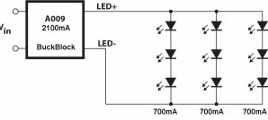
The hybrid approach for a set of 100 LEDs might use ten strings in parallel, with ten LEDs in series in each string. Or it could use 20 strings in parallel, but with five LEDs in series per string, or five strings in parallel and 20 diodes in series in each. The possibilities grow with the number of diodes, as do the tradeoffs.
As the number of LEDs increases, many designs use a “hierarchical” approach, which uses building blocks of series strings combined into parallel sets, and then builds up by using series and parallel combinations of these smaller serial/parallel arrays. This allows for modularity in design and fabrication, as well as for balancing of the supply requirements of voltage, current, and total power.
Part 2 of this FAQ will look more loosely at the various ways to source the power (current and voltage) for LD arrays, as well as dimming considerations.
Leave a Reply