
Regulatory creepage and clearance requirements are increasingly affecting mainstream designs; understanding and meeting them is a complicated, multifaceted process.
This part delves into more details on creepage and clearance.
Q: What are the key standards for defining creepage and clearance minimum values?
A: It’s complicated. Different documents cover PCB creepage and clearance standards and requirements, with some regional differences. Among them are:
- IEC 62368-1:2023 is a top-level product safety standard that classifies energy sources, prescribes safeguards against those energy sources, and provides guidance on the application of, and requirements for, those safeguards. The prescribed safeguards are intended to reduce the likelihood of pain, injury, and, in the case of fire, property damage.
- For circuit boards, the primary standard is IPC-2221, a general standard that covers many different design rules, including the spacing needed for high-voltage circuits.
- IPC-9592 is more specific than IPC-2221 and defines the spacing requirements of power conversion devices that run higher than 100 volts.
- UL-61010-1 specifies the requirements for safety in the design of electrical testing and laboratory equipment as well as other industrial equipment.
- UL-60950-1 is for high and low-voltage applications across a broad range of equipment.
- UL 796 Standard for Safety Printed Wiring Boards
Q: Again, it seems that much of the discussion about creepage and clearance is related to PC boards; is this the case?
A: Yes, it is. The reason is that as board line spacing decreases and density increases while on-board voltages rise, creepage and clearance become more of an issue with the boards, components, layout, and assembly.
Q: How do creepage and clearance vary with voltage?
A: Obviously, the relevant standards call out the minimum values for each as a function of voltage. Higher voltages require wider spacing dimensions.
Q: So, if I know the voltage level, I can calculate the minimum required spacing?
A: It would be nice if it were that easy, but it’s not. In addition to voltage, a critical factor in the creepage calculation is the layer materials that constitute the raw board. The comparative tracking index (CTI) defines the amount of resistance of each material; the higher the number, the greater its resistance to breaking down.
For instance, the default CTI value for common FR-4 is 175, while other more specialized materials can have a CTI value as high as 600. The voltage will create a conductive path along the surface of the board that will break down its insulating properties, and some board materials are more resistant to this effect than others.
Q: This is getting complicated; how do I work CTI into the calculations?
A: It begins with assigning a material group classification to the CTI of your board material, as follows:
- Material Group I: 600 ≤ CTI
- Material Group II: 400 ≤ CTI < 600
- Material Group IIIa: 175 ≤ CTI < 400
- Material Group IIIb: 100 ≤ CTI < 175
Not surprisingly, if the material’s CTI is unknown, is it assumed to be Group IIIb.
Q: Given this data, can I determine creepage and clearance minimums?
A: Not yet. UL-60950-1, specifically tables 2K-2N, provides designers with minimum clearance and creepage values dependent on board-insulation grade, coating, and other factors.
Q: This is somewhat unclear and confusing; can you make it somewhat tangible?
A: Start with the basics of voltage. The working voltage is the highest voltage across insulation when the design is subject to its rated voltage. The creepage and clearance values are calculated by determining the working voltage under a specific operating voltage, which is necessary to calculate both the peak and root-mean-square (RMS) voltages. Based on the working voltage, it is possible to determine a starting point for the minimum PCB spacing.
Q: What are those “other factors” alluded to above?
A: It gets more complicated. In addition to the obvious factor of voltage and the less obvious one of CTI, they include:
- Insulation
- Pollution degree
- Overvoltage category
- Altitude
Q: Can you explain these in more detail, beginning with insulation?
A: Insulation type is defined for five different purposes:
- Basic insulation: Single-layer insulation can provide users with basic protection against electric shock.
- Double insulation includes both basic insulation and supplementary insulation.
- Functional insulation is the necessary insulation between the conductive parts in the equipment so that the equipment can operate normally, so it is not a safety consideration for users.
- Reinforced insulation is a single-layer insulation system that can reach the level of protection against electric shock equivalent to double insulation.
- Supplementary insulation is a second layer of insulation independent of the basic insulation and can protect the user from dangerous voltage when the basic insulation fails.
The insulation standards help protect the circuit and user from abnormal single-fault conditions. These single-fault conditions can be avoided by using double or reinforced insulation, where a second insulation layer is used for additional protection.
Q: How does pollution come into the creepage and clearance analysis?
A: Any kind of solid, liquid, or gaseous foreign substance that reduces the electrical strength or surface resistance of the insulation is classified as pollution. Regular dust, residue from nearby burning, moisture (whether condensation or high humidity), and more are all considered types of pollution with respect to creepage and clearance. Standards IEC 62368-1, DIN EN 60664-1, and VDE 0110-1 (they overlap) describe and define the expected degree of pollution, which then factors into the dimensioning of the clearance and creepage distances.
Q: What are the degrees of pollution?
A: A pollution degree is a number that indicates the expected pollution of the environment, as the lower the value, as lower the expected pollution. The pollution degree is a parameter for additional dimensioning of the required clearance and creepage distances, as specified by the appropriate standard.
- Degree 1: none or only slight, but non-conductive pollution. For example, equipment, components, or subassemblies that are excluded from dust and moisture through sealed packaging. The contamination has no influence.
- Degree 2: Non-conductive pollution, which can become conductive due to occasional or temporary condensation (dew) or hand perspiration. Suitable for general laboratory or office environment.
- Degree 3: Conductive pollution occurs, or dry non-conductive pollution occurs due to expected condensation. For example, equipment is used in the factory.
- Degree 4: conductive dust, rain, or wetness.
Q: What is the impact of overvoltage?
A: Developers of electrical devices must determine how robust or sensitive the electrical device is against overvoltage peaks. The electrical device is assigned to one of the four overvoltage categories (I – IV) as described in the DIN EN 60664-1 VDE 0110-1 standard and is related to the device application location (Figure 1):
- Overvoltage category I: The equipment has taken measures to reduce power transients.
- Overvoltage category II: Permanent or pluggable equipment connected through the building wiring.
- Overvoltage category III: Equipment will be an integral part of the building wiring.
- Overvoltage category IV: Equipment is connected to the main power supply that enters the building.
Q: How does altitude affect regulatory requirements?
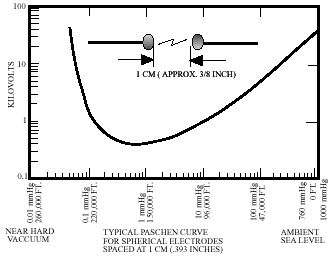
A: It’s well-known that the heat-carrying capacity of air decreases with increased altitude as the air is less dense (also called “thinner”). But the dielectric properties of the air also change with altitude, and breakdown voltages vary approximately proportional to pressure (which is a function of altitude) and inversely proportional to temperature. At higher altitudes, air is not as good an insulator — until you reach a vacuum.
For example, a one-cm gap has a breakdown voltage of about 30 kV DC at sea level, 1.2 kV at 50,000 feet (15,200 meters), and 327 V DC at 100,000 feet (30,400 meters). Therefore, the higher the altitude, the greater the creepage and clearance distance required to prevent breakdown. Figure 2 shows the voltage withstanding/dielectric breakdown of a one-centimeter gap at various altitudes.
Q: What do the creepage and clearance standards say about altitude?
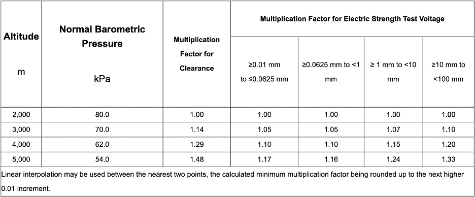
A: The clearance of equipment set in the IEC 62368-1 assumes operating at 2000 meters above sea level, maximum. If there is a high-altitude requirement, the creepage and clearance dimensions must take this into account, and the various creepage and clearance numbers must be adjusted. Table 22 of IEC 62368-1It shows, for example, that an altitude multiplier of 1.48 must be used at 5000 meters, compared to the nominal value specified at 2000 meters; higher multipliers are specified as altitude increases, Figure 3.
The final part of this article looks at ICs which take creepage and clearance into account, some useful design tools, and offers some historical perspective.
Related EE World Content
Key considerations when integrating high voltage dc-dc converters into critical applications
Why I was scared by a technical article
With so many mandates, can successful designs still be achieved?
Why and how are medical connectors and standards different?
Power supply regulations, requirements, and standards
Navigating new safety standards for power supplies
Coming: New safety ratings for power adapters
The basics of AC-line isolation for safety, Part 1: The challenge
The basics of AC-line isolation for safety, Part 2: The solution
External References
Samtec, “Clearance and Creepage” (very useful and has additional linked references)Cadence Design Systems, Inc., “Designing to High Voltage Creepage and Clearance Standards in Circuit Board Layouts”
Coil Technology Corp., “What is clearance and creepage distance of insulation?”
Weidmüller Interface GmbH & Co. KG, “Creepage and clearance distances”
Sierra Circuits, Inc., “The Importance of PCB Line Spacing for Creepage and Clearance”
Texas Instruments, “How to Meet the Higher Isolation Creepage & Clearance Needs in Automotive Applications”
Texas Instruments, “TI’s First Isolated Amplifiers With Ultra-Wide Creepage and Clearance”
Excelsys Technologies, “Design Considerations for Power Supplies in High-Altitude Applications”
Advanced Energy, “How to Select Power Supplies for High-Altitude Applications”
NS Transmission Pvt. Ltd., “High Voltage Insulator”
ADAPT Australia, “Extension Insulators and Extension Link Insulators 15 kV to 69 kV”
Leave a Reply