
Digital isolators have two primary functions, to provide isolation and to transmit information across the isolation barrier. This first of two FAQs on digital isolator specifications looks at voltage and isolation specs. Part two details key specifications related to information transmission. Two basic voltage specs are:
Working voltage (VIOWM) is the maximum rms, or corresponding dc voltage, that the isolator can withstand over its specified lifetime.
Maximum repetitive peak voltage (VIORM) is defined in IEC 60747-5-5 and VDE 0884-11 and quantifies the ability of the isolator to withstand repetitive high voltages across the barrier on a continuous basis.
Isolation is a key specification. Galvanic isolation is needed for user safety and for robust system operation. Key isolation specifications include maximum transient isolation voltage (VIOTM), isolation withstand voltage (VISO) and maximum surge isolation voltage (VIOSM):
- VIOTM – IEC 60747-5-5 and VDE 0884-11 define VIOTM as the peak transient voltage that the isolator can handle for up to 60 seconds without failing.
- VISO – UL 1577 defines VISO as the rms voltage that the isolator can handle for 60 seconds without failing.
- VIOSM – IEC 60747-5-5 and VDE 0884-11 delineate the requirements related to direct and indirect lightning strikes in the form of a surge voltage waveform (Figure 1). To qualify as basic isolation, the peak voltage for the surge test must be 1.3x VIOSM. To qualify as reinforced isolation, the peak voltage must be 1.6x VIOSM. In addition, a digital isolator qualifies as reinforced at the component level according to VDE 0884-10 only if it passes the surge test at over 10 kV.

Insulation thickness, called distance through insulation (DTI), plus the quality of the insulating material are the primary factors determining the ability to meet VDE 0884-10 requirements. A higher quality material has fewer defects and, therefore, a higher breakdown rating. And, of course, thicker materials provide better isolation. VDE 0884-10 is usually met by optocouplers because their DTI is typically about 400 µm, which reduces the importance of the quality of the insulation material. Capacitive isolators also use a high-quality insulation layer (SiO2). While SiO2 has a high dielectric strength, it can’t be deposited in thick layers without reducing its mechanical robustness and reducing coupling efficiency. As a result, capacitive digital isolators can’t receive certification as reinforced insulation.
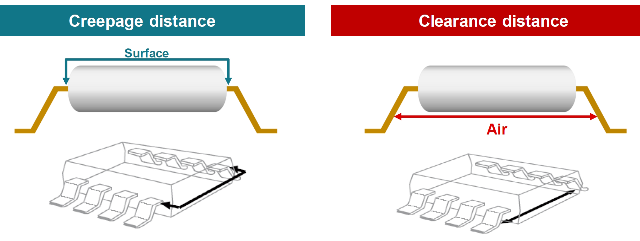
Creepage and clearance
Compared with the electrical specifications for voltage performance defined above, creepage and clearance relate to the mechanical specifications of the package. They are defined as (Figure 2):
- Creepage is the shortest distance between two conductive leads on opposite sides of the isolation barrier, measured along the surface.
- Clearance is the shortest distance between two conductive leads, also on opposite sides of the isolation barrier, measured through air.
Creepage and clearance distances are determined by system-level standards and are based on factors like isolation voltage, material group of the insulator’s package mold compound, and its comparative tracking index (CTI). CTI quantifies the ability of the mold compound to withstand constant exposure to high voltage without surface degradation. Higher CTIs can support smaller packages for a given working voltage.
For IC packages like those used for digital isolators, a creepage distance of 3.2 mm and a clearance of 6.4 mm are typically required for basic and reinforced insulation with a working voltage of up to 250 Vrms. Narrow-body SOICs typically have about 4 mm of creepage and clearance, while wide-body SOICs provide creepage and clearance of 8 mm.
Conclusion
As shown, there are numerous specifications related to the isolation performance of digital isolators. Part two will review the specifications related to information transmission.
References
Basics of the standard digital isolators, Toshiba
Considerations for Selecting Digital Isolators, Texas Instruments
Digital Isolator Design Guide, Texas Instruments
Surging Across the Barrier: Digital Isolators Set the Standard for Reinforced Insulation, Analog Devices
Understanding the Safety Certification of Digital Isolators, Analog Devices
Leave a Reply