• Skip to primary navigation
  • Skip to main content
  • Skip to primary sidebar
  • Skip to footer
  • Subscribe
  • Advertise

Power Electronic Tips

Power Electronic News, Editorial, Video and Resources

  • Products
    • Power Supplies
    • AC-DC
    • DC-DC
    • Battery Management
    • Capacitors
    • Magnetics
    • MOSFETS
    • Power Management
    • RF Power
    • Resistors
    • Transformers
    • Transistors
  • Applications
    • 5G
    • AI
    • Automotive
    • EV Engineering
    • LED Lighting
    • Industrial
    • IoT
    • Wireless
  • Learn
    • eBooks / Tech Tips
    • EE Training Days
    • FAQ
    • Learning Center
    • Tech Toolboxes
    • Webinars & Digital Events
  • Resources
    • Design Guide Library
    • Digital Issues
    • Engineering Diversity & Inclusion
    • LEAP Awards
    • Podcasts
    • White Papers
  • Video
    • EE Videos & Interviews
    • Teardown Videos
  • EE Forums
    • EDABoard.com
    • Electro-Tech-Online.com
  • Engineeering Training Days
  • Newsetter Subscription

What are edge-based and OOK digital isolator architectures?

September 25, 2023 By Jeff Shepard Leave a Comment

Edge-based and on-off-keying (OOK) are common communication architectures used in digital isolators. The choice between the two involves tradeoffs, mostly in data rates versus power consumption. Depending on the implementation, there can also be tradeoffs related to noise and transient response and common mode transient immunity (CMTI).

This FAQ reviews how edge-based and OOK architecture work and looks at some of the tradeoffs that can help determine which is best for specific applications.

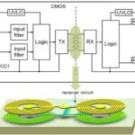
Edge-based communications use at least two data channels. A low-frequency (LF) channel with a bandwidth from DC to 100 kbps and a high-frequency (HF) channel with a bandwidth from 100 kbps up to 150 Mbps (Figure 1). In edge-based designs, a single-ended signal at the input of the HF channel is split into a differential signal. On the other side of the isolation barrier, two comparators convert the signals into differential pulses that are used to drive the NOR-gate flip-flops whose output feeds into the output multiplexer and into a decision control logic (DCL) circuit. The DCL measures the time between signal transients, and if the time between two consecutive transits exceeds a predetermined time limit, the DCL forces the multiplexer to switch from the HF to the LF channel.

Figure 1. Edge-based digital isolator communication uses separate channels for LF and HF information transfer (Image: Texas Instruments).

The LF channel is pulse-width modulated (PWM) using an internal oscillator to provide an HF carrier frequency and create a signal that can pass through the isolation barrier. A low pass filter (LPF) at the output removes the HF carrier from the data stream before sending it on to the output multiplexer.

How does OOK work?
OOK uses an internal spread spectrum oscillator clock to modulate the incoming data stream. The clock frequency is outside the device’s data rate and produces OOK signaling, where one of the input states is represented by the carrier frequency transmission, and a lack of transmission is used to represent the other state (Figure 2).

Figure 2. In OOK architectures, a carrier frequency transmission or the lack of a carrier frequency transmission is used to represent the two logic states (Image: Analog Devices).

On the receiving side of the isolator, a preamp boosts the incoming signal and is followed by an envelope detector that acts as a demodulator to recreate the original digital signal. Signal condition circuits are used to improve the common mode rejection of the channel boosting the CMTI.

Which is best?
That depends. Under some circumstances, like low data rates, OOK can consume more power than edge-based architecture. At higher data rates (above 10 Mbps), the OOK method consumes less supply current than the pulse encoding technique. The simpler logic used by OOK speeds operation resulting in lower propagation delays. In a motor drive, OOK’s lower propagation delay skew minimizes the need for blanking or deadtime in the PWM drive. That, in turn, decreases motor current distortion resulting in smoother motor operation and less bearing and coupling wear, improving efficiency, and supporting more reliable operation. In addition, OOK’s greater noise tolerance can result in more robust solutions. Depending on the isolator design, edge-based and OOK can both support high levels of common mode transient immunity (CMTI).

Summary
Edge-based and OOK are the two most common communication architectures found in digital isolators. Each offers performance benefits in certain applications. In LF systems, edge-based architecture can provide lower power consumption, while in HF applications, OOK becomes lower power. There are also tradeoffs based on propagation delay skew and noise tolerance between the two schemes. Properly deployed, both can provide high levels of CMTI.

References
Digital isolator design guide, Texas Instruments
The Complete Guide to Digital Isolators, ICRFQ.net
The Use of Robust Digital Isolators in the Harsh Environments of Electric Motor Drives, Analog Devices

You may also like:


  • How does digital isolation contribute to sustainability?

  • What’s a digitally isolated transceiver?

  • What technologies are used for digital isolators?

  • What are the key specifications of digital isolators? part 1

  • What is a capacitive digital isolator?

Filed Under: FAQ, Featured, Isolators Tagged With: FAQ

Reader Interactions

Leave a Reply

You must be logged in to post a comment.

This site uses Akismet to reduce spam. Learn how your comment data is processed.

Primary Sidebar

Featured Contributions

Protecting Ethernet interfaces in telecommunications applications against common high energy surges

Ionic cooling: a silent revolution in thermal management

Robust design for Variable Frequency Drives and starters

Meeting demand for hidden wearables via Schottky rectifiers

The case for vehicle 48 V power systems

More Featured Contributions

EE LEARNING CENTER

EE Learning Center

EE TECH TOOLBOX

“ee
Tech Toolbox: Test & Measurement
We’ve gathered articles that include hands-on product tryouts and reviews. Indeed, every article in this issue uses an oscilloscope in one way or another so you might just call this “The Oscilloscope Tech Toolbox.”

EE ENGINEERING TRAINING DAYS

engineering
“power
EXPAND YOUR KNOWLEDGE AND STAY CONNECTED
Get the latest info on technologies, tools and strategies for EE professionals.
“bills

RSS Current EDABoard.com discussions

RSS Current Electro-Tech-Online.com Discussions

  • My Advanced Realistic Humanoid Robots Project
  • Looking for single photovoltaic cells for light gate
  • I am ready to move from electrical and electronics field but confused where ?
  • Hitachi SuperScan Elite 802 CRT Monitor Issues (Model CM802U)
  • Sanity Check – Peltier "Cooler" for Heating and Cooling

Footer

EE World Online Network

  • 5G Technology World
  • EE World Online
  • Engineers Garage
  • Analog IC Tips
  • Battery Power Tips
  • Connector Tips
  • EDA Board Forums
  • Electro Tech Online Forums
  • EV Engineering
  • Microcontroller Tips
  • Sensor Tips
  • Test and Measurement Tips

Power Electronic Tips

  • Subscribe to our newsletter
  • Advertise with us
  • Contact us
  • About us

Copyright © 2025 · WTWH Media LLC and its licensors. All rights reserved.
The material on this site may not be reproduced, distributed, transmitted, cached or otherwise used, except with the prior written permission of WTWH Media.

Privacy Policy