
There are three main technologies used for digital isolators, capacitive, magnetic, and giant magnetoresistive (GMR). This FAQ briefly looks at capacitive designs (they are covered in more detail in “What is a capacitive digital isolator”), then digs deeper into magnetic and GMR devices.
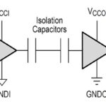
Capacitive digital isolators use two CMOS dies connected with a capacitive isolation barrier (Figure 1). The capacitors are silicon-dioxide (SiO2) based high voltage devices. These isolators provide good performance, are not susceptible to magnetic noise, and have low power consumption.

Coreless transformers
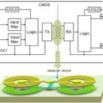
Magnetically coupled digital isolators use coreless transformer (CT) technology, also called coupled inductor technology. Common insulating materials in these isolators include polymers such as polyimide (PI) and SiO2. Both can be used in standard semiconductor fabrication processes and have good insulating properties. For example, a digital isolator using CT technology is based on an integrated on-chip transformer made with metal spirals with SiO2 in between to connect the input and output chips (Figure 2).

These digital isolators have additional functions, including a glitch filter, signal modulation, watchdog timer, and undervoltage lockout. They are designed for use in critical industrial and other applications with high voltages and electrical noise. Features include:
- CMTI over 100 kV/µs
- TTL or CMOS input thresholds for dual-channel devices.
- High or low fail-safe default output options.
- 26 ns typical propagation delay and -5/+6 ns spread.
- Maximum current of 3.3 mA at 3.3 V and 1 Mbps transmission rate.
GMR isolators
GMR isolators provide a larger signal than other isolator technologies. GMR technology is compatible with IC fabrication technology, enabling monolithic GMR devices to be included as part of the IC package.
GMR is a large change in electrical resistance that occurs in spin valves (left image in Figure 2). GMR is a type of spintronics using the spin of electrons instead of their charge. The resistivity of GMR materials depends on the relative magnetic alignment of the ferromagnetic pinned and free layers separated by a non-magnetic conducting layer spacer. Electrons scatter more often when their quantum spin differs from the magnetic orientation of the layer through which they are traveling, resulting in a higher resistance. If the magnetic moments of the ferromagnetic layers are in opposite directions, there is maximum electron scattering resulting in the highest resistance (middle image in Figure 3). On the other hand, if the magnetic moments of the ferromagnetic layers are aligned, electron scattering is the least, and resistance is the lowest (right image in Figure 3).

GMR digital isolators use a Wheatstone bridge built with GMR resistor elements driven with a magnetic coil on the input side. The direction of current flow in the coil on the input side creates a magnetic field that switches the GMR resistors in the bridge. The coil, GMR resistor switches, and support circuitry are integrated with a single IC. The resulting low-power device has the following characteristics:
- Compact size, up to 2 channels in an MSOP-8 package and 4 channels in a QSOP-16 package.
- Data rates up to 150 Mbps.
- Pulse width distortion of 300 ps.
- Propagation delay skew of 4 ns from device to device and 2 ns from channel to channel.
Summary
Digital isolators can be built using capacitive, magnetic, and GMR technologies. Each approach offers different combinations of performance and integration capabilities. All can support high data rates and produce rugged solutions.
References
Capacitive Isolation: A Fundamental Building Block in Future AC/DC Power Conversion, Monolithic Power Systems
GMR in Isolation, Renesas
Infineon ISOFACE dual-channel digital isolators design guide, Infineon
The Importance of Isolation in Data Acquisition Systems, DEWESoft
Leave a Reply