• Skip to primary navigation
  • Skip to main content
  • Skip to primary sidebar
  • Skip to footer
  • Subscribe
  • Advertise

Power Electronic Tips

Power Electronic News, Editorial, Video and Resources

  • Products
    • Power Supplies
    • AC-DC
    • DC-DC
    • Battery Management
    • Capacitors
    • Magnetics
    • MOSFETS
    • Power Management
    • RF Power
    • Resistors
    • Transformers
    • Transistors
  • Applications
    • 5G
    • AI
    • Automotive
    • EV Engineering
    • LED Lighting
    • Industrial
    • IoT
    • Wireless
  • Learn
    • eBooks / Tech Tips
    • EE Training Days
    • FAQ
    • Learning Center
    • Tech Toolboxes
    • Webinars & Digital Events
  • Resources
    • Design Guide Library
    • Digital Issues
    • Engineering Diversity & Inclusion
    • LEAP Awards
    • Podcasts
    • White Papers
  • Video
    • EE Videos & Interviews
    • Teardown Videos
  • EE Forums
    • EDABoard.com
    • Electro-Tech-Online.com
  • Engineeering Training Days
  • Newsetter Subscription

What are the key specifications of digital isolators? Part 2

September 11, 2023 By Jeff Shepard Leave a Comment

Digital isolators have two primary functions, to provide isolation and to transmit information across the isolation barrier. Part one looked at the various specifications related to voltage and isolation performance. Part two details key specifications related to the transmission of information.

Common‐mode transient immunity (CMTI) is one of three key specifications of digital isolators. The other two key specifications, isolation rating and working voltage, were discussed in part 1 of this series. CMTI is the ability of an isolator to handle high slew rate voltage transients between its two grounds without corruption of the signal. Too low a CMTI can lead to bit errors in the transmission. High CMTI indicates a robust isolation channel.

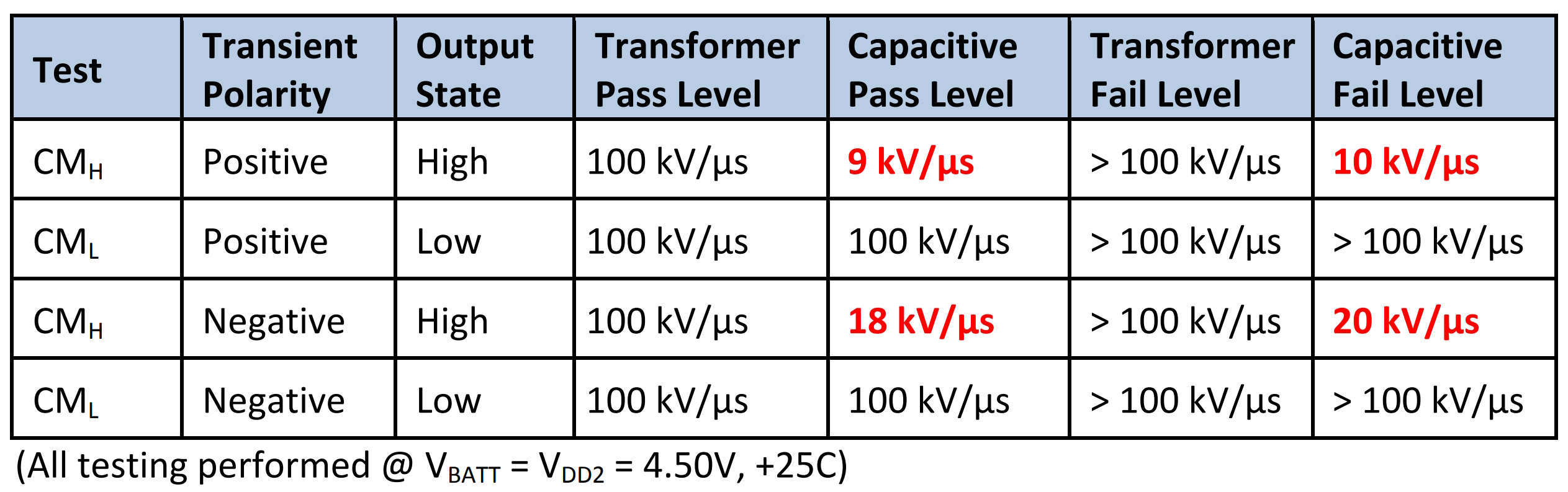
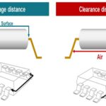
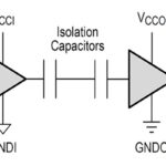
CMTI testing is done for positive and negative transients with the inputs of the device being tested tied to HIGH and LOW. Two common digital isolator technologies are an air core transformer, or coupled inductor, and silicon dioxide capacitors. A commonly used CMH test criterion is the maximum sustainable common-mode voltage slew rate while keeping Vout at greater than 80% of VDD2. For CML, the requirement is to keep VOUT under 0.8 V. As shown in Table 1, transformer-based isolation outperforms capacitive designs.

Table 1. Transformer-based digital isolators have better CMTI performance than capacitive-based designs (Table: Analog Devices).

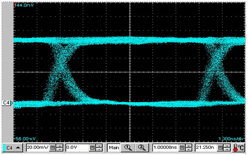
The importance of a high CMTI is evident in the performance of a digital isolator that features a minimum 100kV/μs CMTI and can support a data rate of 150 Mbps. In Figure 1, the oscilloscope was set to 1.0 ns/div. The eye pattern demonstrates that data integrity was maintained with a 2 ns pulse width distortion and 350 ps peak jitter.

Figure 1: Eye pattern for 150 Mbps digital isolator operation (Image: Skyworks).

The following is a selection of additional digital isolator specifications related to data transmission, including propagation delay, channel matching, and output enable and disable times:

  • Pulse width (PW) is the minimum pulse width needed for normal operation.
  • Propagation delay time (H to L), tPHL is the time needed for the output to change from high to low after the input signal changes.
  • Propagation delay time (L to H), tPLH is the time needed for the output to change from low to high after the input signal changes.
  • Pulse width distortion (PWD) is the absolute difference between tPHL and tPLH in a channel.
  • Propagation delay skew, tPSK is the dispersion in propagation delay times between different isolators.
  • Channel matching:
    • tskSD is the difference in propagation delay time between channels in the same direction.
    • tskOD is the difference in propagation delay time between channels in the opposite direction.
  • Output enable time:
    • tpZL is the time it takes for the output to change from high impedance (Z) to low-level after a change in the control signal.
    • tpZH is the time it takes for the output to change from Z to high-level after a change in the control signal.
  • Output disable time:
    • tpLZ is the time it takes for the output to change from low-level to Z after a change in the control signal.
    • tpHZ is the time it takes for the output to change from high-level to Z after a change in the control signal.

Summary
The three key specifications for digital isolators include isolation rating, working voltage, and CMTI. The first two were reviewed in part 1 of this FAQ series. CMTI and other specifications related to information transmission were detailed above. CMTI is an especially important spec and is strongly correlated with data transmission speeds. It differs for transformer-based and capacitive-based isolators.

References
Common-Mode Transient Immunity, Analog Devices
Digital Isolator EMC Application Notes, Toshiba
Digital Isolator Design Guide, Texas Instruments

You may also like:


  • How does digital isolation contribute to sustainability?

  • What’s a digitally isolated transceiver?

  • What technologies are used for digital isolators?

  • What are the key specifications of digital isolators? part 1

  • What is a capacitive digital isolator?

Filed Under: FAQ, Featured, Isolators Tagged With: FAQ

Reader Interactions

Leave a Reply

You must be logged in to post a comment.

This site uses Akismet to reduce spam. Learn how your comment data is processed.

Primary Sidebar

Featured Contributions

Protecting Ethernet interfaces in telecommunications applications against common high energy surges

Ionic cooling: a silent revolution in thermal management

Robust design for Variable Frequency Drives and starters

Meeting demand for hidden wearables via Schottky rectifiers

The case for vehicle 48 V power systems

More Featured Contributions

EE LEARNING CENTER

EE Learning Center

EE TECH TOOLBOX

“ee
Tech Toolbox: Aerospace & Defense
Modern defense and aerospace systems demand unprecedented sophistication in electronic and optical components. This Tech ToolBox explores critical technologies reshaping several sectors.

EE ENGINEERING TRAINING DAYS

engineering
“power
EXPAND YOUR KNOWLEDGE AND STAY CONNECTED
Get the latest info on technologies, tools and strategies for EE professionals.
“bills

RSS Current EDABoard.com discussions

RSS Current Electro-Tech-Online.com Discussions

  • high voltage
  • How many do you remember.
  • How do I choose the right stepper motor for my DIY 3D printer?
  • Honda 250 motorcycle blowing bulbs
  • Glue for motor magnets

Footer

EE World Online Network

  • 5G Technology World
  • EE World Online
  • Engineers Garage
  • Analog IC Tips
  • Battery Power Tips
  • Connector Tips
  • EDA Board Forums
  • Electro Tech Online Forums
  • EV Engineering
  • Microcontroller Tips
  • Sensor Tips
  • Test and Measurement Tips

Power Electronic Tips

  • Subscribe to our newsletter
  • Advertise with us
  • Contact us
  • About us

Copyright © 2025 · WTWH Media LLC and its licensors. All rights reserved.
The material on this site may not be reproduced, distributed, transmitted, cached or otherwise used, except with the prior written permission of WTWH Media.

Privacy Policy